Today, on the chopping block we have an everyday (for some) medical equipment.
It's the Accu-Check Compact blood sugar meter. I got this, for about 6 Euros, because I was interested in what' inside one of these and how such a device actually measures blood sugar. Also I had a hunch that it may have some niece electronics inside which I could use in some other projects.
Now, let's see what this baby looks like on the inside.
At first, doesn't seem like much, but things are really nice and compact inside. This is how it looks with the front off. The cavity on the right (Marked with blue) is where the drum of test strips goes in.
A motorized rod (Marked with red) pushes a strip out of the drum and through the glucose sensor (Marked with purple)
Now, to detect glucose in the blood, there are two main ways.
One is electrochemical in nature. You get the glucose in the blood to react to an agent on the test strip. Electrodes on the strip allow a bias voltage to be fed through and then the current is measured, which is proportional to the amount of glucose in the blood. The full scale current would be somewhere around 10-50 µA (http://www.maximintegrated.com/en/app-notes/index.mvp/id/4659)
The other way to do it is by optical measurement. When a blood sample is placed on the test strip, this will change color according to the glucose concentration. A LED diode biased with a known current is shone onto the test strip and a photo-diode senses the reflected light, who's intensity is dependent on the color of the strip. From what I've read, the biasing current is somewhere from 1µA to 5µA. This is the method also used in the Accu-Check Compact.
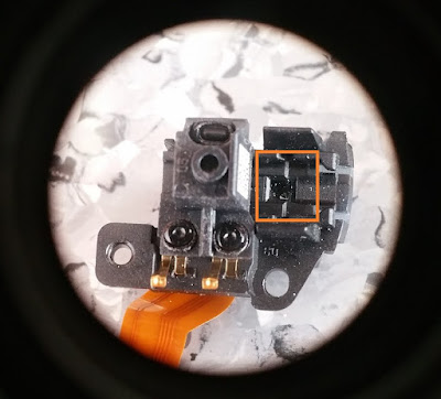
This is a close-up of the sensor. I've marked the window for the LED and photo-diode.
And this is the actual array, with the LED on the right and the photo-diode on the left.
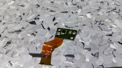
And not, let's see how the PCB for this thing looks like.
Looks well made and designed. On the right, you can see the OLED display this thing uses. It's based on the SSD1325 controller, for those that are wondering, so it should be relatively easy to take this out and use it for something else. The big black square on the PCB is actually a piezo-transducer, (Datasheet here) for whatever sounds this thing makes.
A nice thing to notice are the multitude of test pads on the board. Being a medical device, probably there's a lot of things that need to be spot on for it to pass whatever standards that concern this specific field. Also, probably there's a bit of calibration going into this meter.
There's also an infrared comm. port on this thing, probably for downloading all the history data onto a PC or something like that. Haven't tried playing with that, so I can't tell for sure, but from the manufacturer's data, that might indeed be the case.
Also, after some searches, I found out that someone else took apart one of these glucose meters and hacked the display, which I'm going to do pretty soon. Information on that can be found here: http://home.arcor.de/wehrsdorf/Oled-Display-Recycling.html
There's also a bit of grunt built into this meter, when it comes to processing power.
That's most likely an ARM processor from Atmel, for the doing all the math and driving the infrared port and motors and whatever else on the board needs some smarts behind it. For the actual OLED display, there's an ATMEL Mega 168 micro, which I will soon acquaint myself with, in order to get the display going.
What I was really curious about was the ADC that reads the photo-diode and also driver for the LED diode. From what I read, there must be some really precise measurements done in order to get accurate readings.
Link to Picasa Teardown Album


0 comments:
Post a Comment