Well. it turns out that Christmas came a bit later this year. Probably one of the reindeers had a flat hoof, or something.


OK, so I bought myself a signal generator for the measly sum of 70 Euros, including shipping. The guy I bought it from said the unit didn't work. No problem, I said to myself. It'll make a nice organ donor for other projects. Probably filled with all kinds of goodness inside.....matched JFET pairs maybe.... a nice 10 MHz reference. I was drooling over it.
Now, let me tell you, when it came, I almost had a hernia. It's heavy as frig....about 20 Kilos worth of 2 DIN (I guess) rackable signal generator.
So, I got the beast in the house (all the way up to the 5th floor and no elevator, mind you) and first thing I looked at was the fuse....which, of course, was nice and toasted. Before replacing it, I looked at the mains voltage selection switch. My optimism spiked when I saw it was set to 230 V AC.
So, now, knowing that the main transformer and PSU inside it might be OK, I replaced the fuse, turned it on and....nothing, obviously.
So, following the "Thow shall always measure voltages" rule, I got the DMM out and first thing I measured was the input to the transformer. It measured 0 V on its input.
Seeing as how the on/off switch was all gooey, I measured the voltage on its pins. Nothing as well.
Ok, I'll bite.... I preceeded to desolder the wires from the switch, rummaged through my junk pile and found a suitable replacement then soldered back the wires on that one.
Because I didn't find the appropriate fuse size, I cobbled something with I could find. No pretty, but it did the job.

Yes, apparently, it was just that simple. So, now that I had a working Signal generator, let's see what it can do.
The first thing I noticed when turning it on was how loud the fan was. It sounded as if I had a tractor plowing right next to me.
Unfortunately, I couldn't fin any FREE user's manual or service manual for this unit. There is on on eBay for sale, but as of writing this , it cost about 80 dollars including shipping. Needless to say, the guy selling it can just shove it, I ain't paying that much. I;m sensible for these kinds of things.
Ok, so from playing around with the unit, it looks like it can do a frequency range from about 10 mHz all the way up to (what should be) 10 MHz. If it goes higher, I couldn't find the right combination of random key presses tht made it go beyond 10 MHz.
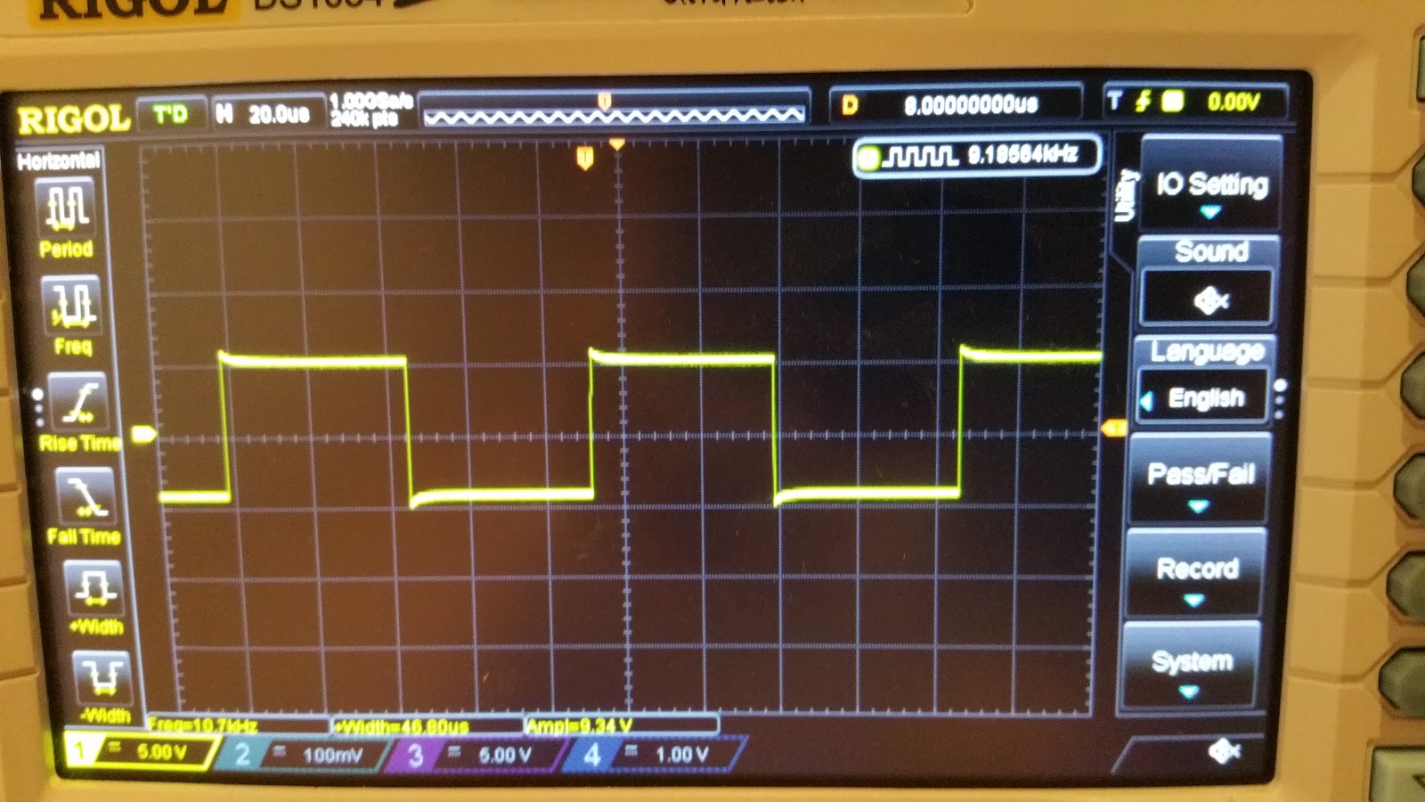
Amplitude wise, looks like it can go as low as 100 mVpp and as high as 100 Vpp, all into 50 Ohms. Yes, really. At least that's what my scope measures, anyway.
On the output BNC, it didn't mention anything about it being 50 Ohms, but I just presumed it was. Also, if I feed the output directly into the scope, without a 50 Ohm termination, the square waveforms look distorted.
So, what else can this beast do? Well, it has you basic Sine, Square, Triangle and Pulse Width waveforms. Also, it has a nice and handy Burst Mode. As for the rest, I really can't say. I probably need to RTFM.... If only I could find one that didn't cost more that what I paid for the unit itself.
And now, on to our scheduled Teardown:
The unit has a modular construction. And judging from the number of empty slots, looks like you could attach a whole freaking lot of options to this generator. Too bad I only got the basic version.


Next up is the PSU board. Amazingly enough, for a unit that's well over 30 years old, the caps look OK. All of them.


The next board to get lifted out, after who knows how any years, is the A2 "Program Logic Card"

Looks like this is some glue logic, because the board if full of buffers, MUXs and other 74LS family logic.
Next up is the A20 - IEEE-488 interface card.


Starting from the left corner, there's a DIP switch, for setting the address of the device, two resistor networks (that's what Google came up with): 316A622 and 316A302, and a whole bunch of logic gates. 74LS family, of course.
Now we're starting to get into the meat of it. A7 - Question Mark Card


Nope, no idea what "S/S" means or what it does. But it looks cool, doesn't it?
Maybe signal conditioning? Or maybe it's something that has to do with the DC Offsets and stuff?
Next on the list is the A8 - Frequency Syhtesizer Card


You gotta love those hand drawn traces. Finally, we get to see some of that goodness I was hoping.
The digital part has the usual logic gates, flip-flops, etc. The analog part... well...
The main part is the AM26S02PC Monostable Vibrator.
This, together with that ferrite and some CA3039 diode arrays seem to make up what would be a ring modulator. I don't know too much about RF stuff or frequency symthesizers, so if anyone has a better idea of what the synthesizer might actually look loke, pleas leave a comment. I'm really interested in how this thing works. If only I had a manual for this thing.
Also, some keen observers might see that there's a whole boatload of diodes on this part of the board and I doubt they're all Zeners.
The next board is the Waveform Selection A9 Card.


From the looks of things, it looks like the board is mainly switching some stuff in and out, i.e. ony selecting the appropriate waveform. The yellow cylinders are most likely relays and the two 8-pin ICs are DS75451N drivers, for said relays.
The bigger IC on the far right is a CA3086 transistor array.
The three single line ICs are resistor networks. One might speculate that these together with the diodes make up some snubber for the relays' coils. Though this is arguable.
The next card is the one that does all the heavy work - The Output Amplifier A10 Card


Some bus interface logic, a few Motorola 2N5160 and 2N5109 RF transistors and some analog goodness make what is to be the generator's output board.
The front end of the amp is an RCA CA3102E differential amplifier IC.
Also notice the point-to-point connections in the third and fourth picture.
And last, but not least, we have the (Amp?) DAC card - A11


The usual bus interface and glue logic ICs. Boring.. But wait. What's this? an RCA CA3130S. Now this is something. It's a metal can op-amp. But more that that, it's a PMOS input op-amp. Here's something you don't see every day. Well, I don't, anyway.
And some more Analog goodness - an SN72558P op-amp
Ok, so maybe it's not something to write home about, but I thought I'd try and distract you fro the fact tht there is no actual DAC on this board. It might actually be on the board that's blted to the front panel. And I'm too lazy to actually take that out. Another option might be that all those resistors up there make an R-2R ladder DAC, but they all seem to have the same value, so that theory's shot.
So this board ight indeed be just a pre-amp for the signal coming from the DAC.
It looks like the reference is a simple 1 MHz crystal olscillator. I might consider changing that to some TCXO or OCXO. We'll see.
Ok, so basically, I have a working unit, though there's still a lot of loose ends to it. For starters the amplitude and frequency are WAY off from what I set on the front panel.
For the frequency, there seems to be a ~2.5% to 3% deviation across all frequency ranges. For the output voltage.....well, the deviation is about 20 to 25% on all frequency ranges.
These might be simple, except there's a whole heapin' mess of trimmers. Yes, you've guessed it.. I really need a mannual for this thing.
Here's a few mre pics of the beast in action:


In caase someone happens to have a manual for this thing and is willing to share, please contact me either by leaving a comment or on the blog's facebook page. Thanks.
If you'd like to see the full album of the teardown, here it is.
Later edit: Turns out that a kind sould has the same model generator and was willing to share the manul with me and anyone else in need of it. You can download it from here.
Thanks Alexander!


