I got this old relic for free from a very kind person, when I was still a student and working on my final year project. It's a great bit of kit, and, yes, it's a clone of the Tektronix modular scopes from the 80's, and yes, the labels are all in Russian, and yes, it takes 10 minutes for the CRT to actually show something....but hey, it did it's job.
But now, since I got my new Rigol 1054Z and because the trigger on the old C1-91 has been trowing fits, I figured that it was just taking up space. Plus I just couldn't find a spot in a corner somewhere where it could sit undisturbed and hot have to move it every time I cleaned my room / lab, because this thing is heavy....about 30 kilograms worth. So I decided I could do without it and maybe use the components inside for other things, like an oscilloscope clock for example.
So, taking after it's clone, the Tektronix 7000 series Mainframe oscilloscopes, it has three bays where one can mount different modules, from a two channel oscilloscope input module, to a multimeter module, signal generator modules and so on. I removed mine, then proceeded to disassemble it to it's bare bones. Easier said that done, and I'll explain why.
The people that designed this scope were either thinking, or blindly copied every detail from the Tektronix scopes. I, personally, since I haven't seen the insides of said Tektronox scopes, would like to believe the first option, that the russian engineers knew what they were doing.
Because the frame of the scope was all aluminium, it only makes sense that to avoid corrosion pr oxidation, same metal fastners have to be used. Therefore, all the screws on the aluminium parts were also made of aluminium. Which would be nice, if they weren't made from the softest alloy they could find. And when I say soft, I mean that by applying a bit of force to loosen the Phillips head screws was enough to mangle them and so, be stuck in place.
Oh well....where there's a hammer, there's a way.
The first thing one notices when taking such devices apart is how different they look. Back then, the Russians made their own electronic components (capacitors, resistors, diodes, transistors of all kinds, ICs), after their own liking and in the process, developed a style of their own, to laying out boards.
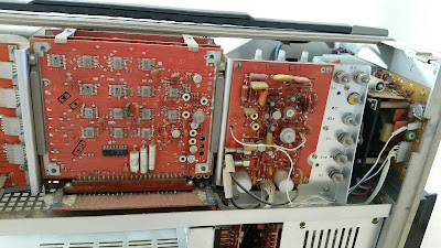


See what I mean. By the way, the square metal cans are actually hybrid circuits.
Trust me when I say it's weird. And don't even get me started on the schematic. In fact, as I'm writing this, I'm trying to figure out the schematics for this thing, so that I can turn it into a prototype for an oscilloscope clock and sincerely, not getting anywhere with it. I mean, they have all kinds of numbered wires going all over the place to numbered connectors. But the same wire has different markings on each end and each pair of connectors (from one board to another) also have different names, making things very frustrating and hard to read. A post with my efforts on the scope clock will follow at some point.
Until then, I leave you with the Picasa album with teardown pictures for this thing so you can admire this in its full glory and actually get a feel for how bulky this thing is and feels.
The first thing one notices when taking such devices apart is how different they look. Back then, the Russians made their own electronic components (capacitors, resistors, diodes, transistors of all kinds, ICs), after their own liking and in the process, developed a style of their own, to laying out boards.


See what I mean. By the way, the square metal cans are actually hybrid circuits.
Trust me when I say it's weird. And don't even get me started on the schematic. In fact, as I'm writing this, I'm trying to figure out the schematics for this thing, so that I can turn it into a prototype for an oscilloscope clock and sincerely, not getting anywhere with it. I mean, they have all kinds of numbered wires going all over the place to numbered connectors. But the same wire has different markings on each end and each pair of connectors (from one board to another) also have different names, making things very frustrating and hard to read. A post with my efforts on the scope clock will follow at some point.
Until then, I leave you with the Picasa album with teardown pictures for this thing so you can admire this in its full glory and actually get a feel for how bulky this thing is and feels.


Salut, am un osciloscop identic cu anumite module lipsa si m-ar interesa niste module de la al tau. Sper sa-l readuc la viata pt ca mai bricolez cate ceva si am nevoie de un aparat ca acesta la diverse verificari. Daca mai ai module si te intereseaza un schimb cu altceva sau poate bani contacteaza-ma prin adresa de email gblioju@gmail.com . Multumesc, Gica.
ReplyDeleteSalut,sunt interesat de osciloscop daca mai exista bineinteles! email:marius_52@ymail.com sau tel:0728351426
ReplyDeleteThanks for the nice post http://besttopreviewsonline.com/blog/10-best-oscilloscope-for-hobbyist/
ReplyDelete