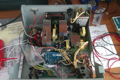
About a year ago I bought and old Voltcraft DPS-4005PFC adjustable switchmode power supply, advertised as not working. It was missing the main controllers and also the two main switching transistors, but I thought I would give it a shot. I mean, if all else failed, I could rip out the rest of the bits in it and spin my own PSU.
I thought it was a nice bit of kit: 0-40 Volts and 0-5 Amps, PFC, a nice big LCD....
When I got it, I gave it a thorough visual inspection and the once-over with the DMM, to check for any burnt or missing components.
After it all checked out, I put it on a shelf somewhere, waiting to buy some 2SC2625 for it and see if it did anything (besides blowing up in my face).
A moth ago, I decided to buy the transistors. Got them, soldered them in, now, to test it.....But how?
Well, Arduino was the answer, of course.
I got the schematics out, identified the pins for the AD7541 DAC, wrote a quick and dirty code for it, and voila!, voltages on the output. Perfect.
Now, let's get the whole thing working. I mean the LCD, the rotary encoder, the buttons. the current limiting, the fan and, apparently, the fine voltage setting mode this thing has (I'll talk about this later)
So, back to the schematics. This thing used two micro-controllers to drive this thing. A Windbond W78C32B-40 to drive the LCD and do some EEPROM storage and an Atmel AT89C51 to do the rest of the control and housekeeping. So the Leonardo that I have hooked up to this thing isn't going to cut it. The plan is to get all the parts working, one by one, then buy a Mega and put it all together, into one code and fire this thing up (figuratively speaking, of course).
Just to see what it takes to drive this thing, below is a table with all the connections I need to hook up to get the PSU into working shape.

The pin assignment on the Mega is mostly chosen randomly, so they will probably change by the time I get it into final shape.
So, let's get to the interesting part. First off is the encoder and output relay. Simple things.
For the encoder, I used the library from this site. It's very easy ans simple to use and it worked first time, without any headaches.
Next, was the LCD. Boy, did that ever got me frustrated. It's simple, if you read the datasheet, but who has time for that. The chipset for the LCD is the PCF8576.
I did a quick search for anyone else thet had to deal with this controller, and there were some references and some code available, so I didn't had to start from scratch.
It's nice that it's an I2C device, so it was easy to wire in (of course I mixed up the SDA and SCL pins the first time)
Because the LCD has 4 backplanes, the setup for this LCD is 1:4 drive mode, with 1/3 bias configuration. That means, that if you start sending it data starting from address 0x00 (B00000000), each consecutive byte of data will increase the address counter in the PCF8576 by 2. This took me a while to get used to. Also, I made it more complicated because I actually wanted to understand how this thing works, so I got out an A3 paper, made a copy of the LCD segments on it and started feeding it address and data bytes (please excuse the bad hand writing).

At first, I had no clue what I was doing and luck would have it, I started with an odd address value, which gave me the weirdest results: a byte controlled the segments on half a digit and half on the adjacent digit.
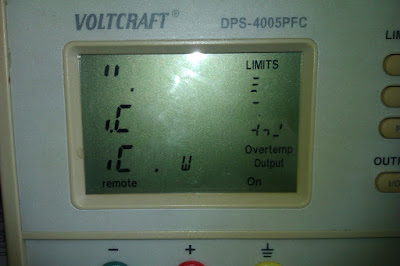
After a few frustrating hours, I eventually got fed up with this, started from address B00000000 and fed it about 20 bytes of data and lo and behold, the whole LCD lit up, AWESOME!
An hour later I had all the individual LCD segments mapped out.
#include <Wire.h>
#define ADDRESS B0111000 // I2C Address of PCF8576
#define DEVICE_SELECT B11100000 // Device select [Command] [1100] [A2 A1 A0]
#define MODE_SET B11001000 // MODE SET [C] [10] [LowPower] [Enable] [Bias] [Mux]
#define BANK_SELECT B11111000 // no effect in 1:4 multiplex mode
unsigned long time;
unsigned long time_now;
void setup()
{
}
void loop()
{
Wire.begin(); // join i2c bus (address optional for master)
delay(1000); //allow lcd to wake up
Wire.beginTransmission(ADDRESS); //adress the upper I2C-controller.
// delay(2);
Wire.write(MODE_SET); //MODE SET (Command)(10)(LowPower)(Enable)(Bias) (Mux)
// (1) (0) (1) (ΩBias) (1:2)
Wire.write(DEVICE_SELECT); //Device select (Command)(1100)(A2 A1 A0)
// (1) (0 0 0 )
Wire.write(BANK_SELECT); //Bank Select (Command)(11110)(Input)(Output)
// (1) (0) (0)
Wire.write (B00000000) ; //Address - starts gro 0x00
Wire.write (B11111011) ; //5 and limits and dots and Output//A-0
Wire.write (B11111111) ;//6 and i-const //A-2
Wire.write (B11111111) ;//9 and remote //A-4
Wire.write (B11111111) ;//10 and locked //A-6
Wire.write (B11111011) ;//11 and p-const //A-8
Wire.write (B11111010);//12 and W //A-10
Wire.write (B00000000); //Overtemp, ON, 18 and 19 //A-12
Wire.write (B11011011);//20 and w // A-14
Wire.write (B11111100);//18 and 19 // A-16
Wire.write (B11110110); // Off, 15 and 16 // A-18
Wire.write (B11101011);//17 and a // A-20
Wire.write (B11111011);//15 and 16 // A-22
Wire.write (B11111011);//14 and v // A-24
Wire.write (B11111011); //13 //A-26
Wire.write (B11111011);//4 and V // A-28
Wire.write (B11111011); //3 and up arrow // A-30
Wire.write (B11111011); //2 and down arrow // A-32
Wire.write (B11011101); // 1 and fine // A-34
Wire.write (B11111011); //8 and A // A-36
Wire.write (B10111011); //7 and u-const // A-38
Wire.endTransmission();
}
I've put comments next to each data byte regarding what digit number o character they encode, after my own notation, of course. Here are the pics with the corresponding character numbering:

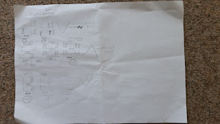
There are two mappings because I've split up the screen into two areas so I would have more space on a single A4 paper. The first pic is of the left side of the display, where the main voltage, current and power reading are displayed and also other characters like the "Limits", "V", "A", "W" characters, etc.
The second pic is of the right side of the display, with the limits settings. Underneath each digit or character is the number I assigned to it and corresponds to the numbers in the Arduino code.

Looks better now, doesn't it? And yes, it was supposed to look like that i.e. "6"s and inverted "A"s.
And now a quick explanation of how the bits map out in a byte.
Say you have:
The address is 0x22 which is 32 in decimal. The bits from 0 to3 and 5 to 7 map out segments of a digit (in this case digit 1) while the 4th bit is for a character on the screen (in this case "Fine")
So, at address 0x22, bit 0 set to "1" turns on segment D of digit 1 (which according to my hand drawn diagram of the LCD is the left most digit on the first row). Bit 4 set to "1" will turn on the "Fine" symbol and bit 7 set to "1" will turn on segment B of digit 1.
Hope this makes some sense. If not, you can always leave a comment or contact me via my Facebook page: https://www.facebook.com/ElectronicsPlayground?ref=hl
Also, there's going to be some updates coming, once I put everything together on the Arduino Mega and move the actual code on it.


Hope things are going well with your project; seeing stuff like this happening gives an old tinkerer hope for the future.
ReplyDeleteI've got two DACs cobbled together for the current and voltage settings, all I have to do now is write the software for it. I'll try and wrap things up soon, because this kept getting put aside for too long
DeleteIndeed.
DeleteThis comment has been removed by the author.
ReplyDeleteHello Razvan, can I ask you a question about the power supply Voltcraft 4005? I happen to have the same model (4005) in my homelab. If possible I'd like to use the supply for driving an anodization process. For this goal I will need a supply that I can program. I must be able to program the voltage and the time. Can the Voltcraft 4005 do this do you think? -For example: the power supply must deliver 5 Volts during 10 minutes (interval A); 40 Volts for 3 minutes (interval B); 5V for 10 min (interval A); 40V for 3 min (interval B).... and so on. I need to program that sequence of intervals ABABAB. (Choose voltage value, and time value, of the interval A, and the interval B.) However I have never tried programming the 4005. Can it do that do you think? Can the supply deliver the sequence of intervals? would be grateful for your comment. Hope to hear from you later. Thanks in advance for the answer. Regards Gerard.
ReplyDeleteYes, you can most definitely control it. As it stands, the Voltcraft PSU comes with a built-in isolated RS-232 port. You can feed it commnads through it. here's a document detailing more of how it's done: http://www2.produktinfo.conrad.com/datenblaetter/500000-524999/510890-an-01-en-Schnittstellenbeschreibung_DPS_4005.pdf
ReplyDeleteYou can make a script (batch file script, Python, whatever flavor programming language you know) that sends certaind RS-2323 commands at certain times
On mine, as I have replaced most of the logic board with the Rduino, do not have this feature....yet.
Razvan thanks for the help, good to know it can be done via the interface. Will proceed that way then. By the way my LCD display shows signs of bleeding (as if an inkblot is leaking behind the glass panel) I can still read the displayed values okay. But just in case, for when the bleeding would worsen and hinder reading the display - would you know an address where one can access a spare display? thanks for your help. regards, Gerard
ReplyDeleteUnfortunately, these kinds of displays are usually made for to order. So, as I see it, there's 2 possibilities for when it fails: 1. You get another PSU and change you display with that one. 2. You replace the whole logic board with something like an Arduino or an ESP board or an ARM board and fit it with the LCD of your choosing.
ReplyDeleteyes that's a good option for spare parts. I visit ebay from time to time looking for an old voltcraft 4005. By the way there exist power supplies that look just like the voltcraft 4005, they share the performance characteristics. These are worth tracking too I think. Here are some examples of these lookalikes:
ReplyDeleteGW Instek PSP405 (GoodWill Instek; Taiwanese)
DF1797B-4005 (also called: DF1797B) (Ningbo Zhonge Dftek Electronics; Chinese)
McVoice SNNT4005
Velleman PSS4005
Promax FA405
Thanks and all the best, Gerard.
It is very easy to replace the front polarizer film of the display.
ReplyDeletePull off the old one, remove the glue with a hot razor blade.
I did use a selfadhesive 90 grd film and cut a piece at 45 grd.
Hi evrione,
ReplyDeletewhat is the easiest way to switch the power supply without the controller part (defective) to the max voltage. I put a cheap dps module from ruidong into the housing. https://de.aliexpress.com/wholesale?catId=0&initiative_id=AS_20180919103558&SearchText=dps5005
ludwich