If you can do it, then why not over-do it. At least that's what I did with this project. It started out small....just a simple motor, stick a bobbin on the end of it then wind away to you heart's content....Naaaa!
Indeed, I do. And since this will be a "hand winding" operation, it implies that both hands will be preoccupied with the....well, winding, of course. Therefore, who's going to control the motor?
And since humans happen to have four limbs, an obvious candidate to fill in the position would be - a foot...by means of a pedal. Ergo, I need to make myself a foot pedal to properly control the motor. And not just an ON/OFF kind of control. No no no....I want speed control.
Choices... so many choices....
Ok, so how about the heart of this thing? The motor. What kind of motor should I use? Well, a DC motor from an electric drill would have been enough. But like I said, why not overdo it. So, I had a Stepper motor driver available. It's an AMIS-30543 stepper motor driver that can do up to 3A per coil. Works for me.
Now what kind of stepper? Some might think, "a NEMA17 stepper would do it". Not!
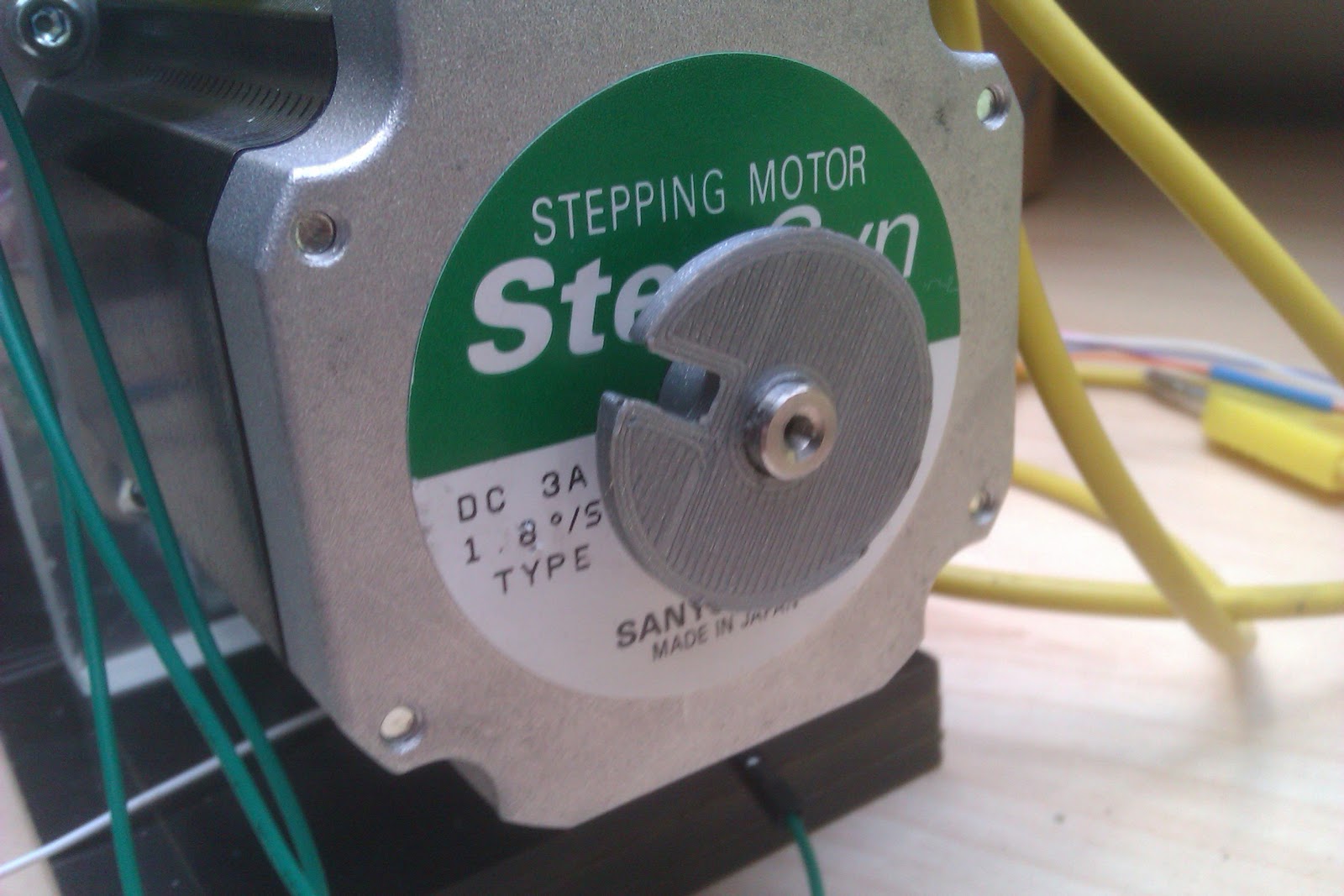
From my pile of steppers, of course I went ans picked the biggest most powerful stepper I had. It's a NEMA23, 3Nm stepper motor. You might think it's overkill. But Since I do a lot of SMPS and high power stuff, there will come a time when some 0.7mm or 1mm magnet wire will have to be wound. And that requires a lot of torque at low speed. Yes, an electric drill ca provide that. I know, I know. I just don't want to use that.
Strange things are afoot
Now for the control part - The pedal.
I initially though I could do the pedal with springs... big powerful springs. Of course, that didn't really pan out. The spring itself was OK, but the wire setup would either get snagged or the wire (guitar string wire) would stretch out and wouldn't tension the spring properly.
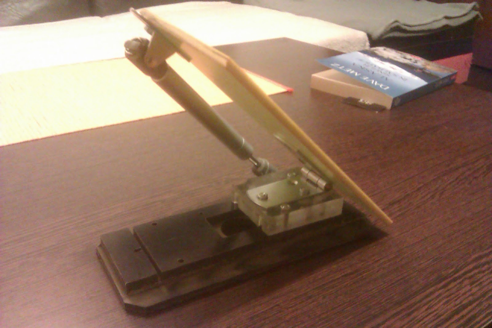
But, being the engineer that I am, I often get inspiration from things around me. This time, it was a cupboard door hinge that used a telescope to help raise and lower the door. BINGO!
I went to the hardware store, bought two of those furniture telescope things, came home, threw away the spring and wire and mounted the new mechanism. And it worked. Brilliantly, I might add. It feels just right. The pressure i have to put on the piston feels just about right. And it's very smooth and controllable.

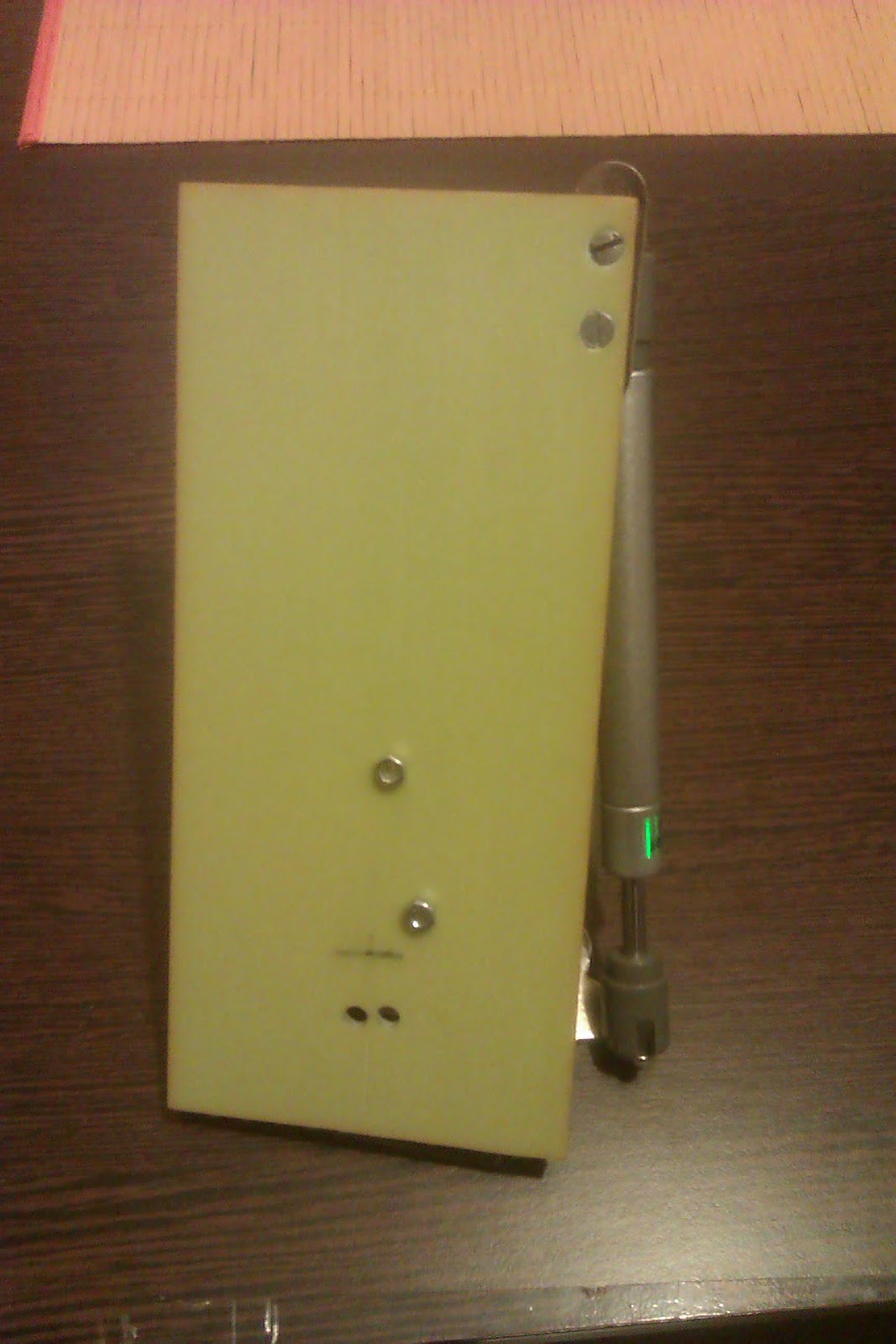
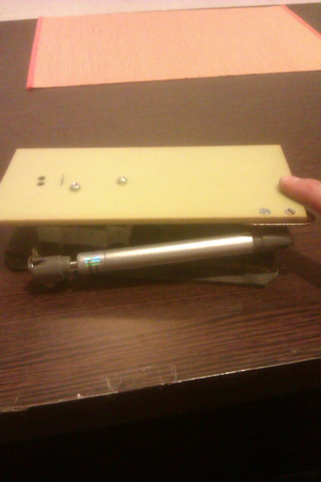
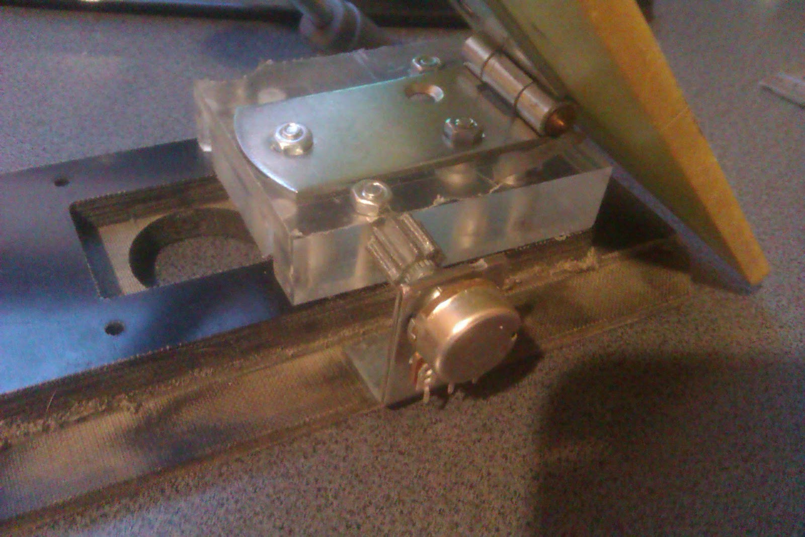
The two nuts sticking out in the middle of the pedal will eventually get replaced by countersunk screw...eventually.
The base is made out of 15mm (590 thou, for those that still refuse to get with the program) thick resin impregnated fibres (cotton fibres, I think). Atop of that is a square polycarbonate piece, that holds the hinge. The pedal itself is made out of some kind of 5mm thick fibre-glass resin material.
If you're wondering about the routed edges and other stiff going on on the bottom black piece, well, don't They were already there. (I'm not that lucky as to posess a milling machine....yet)
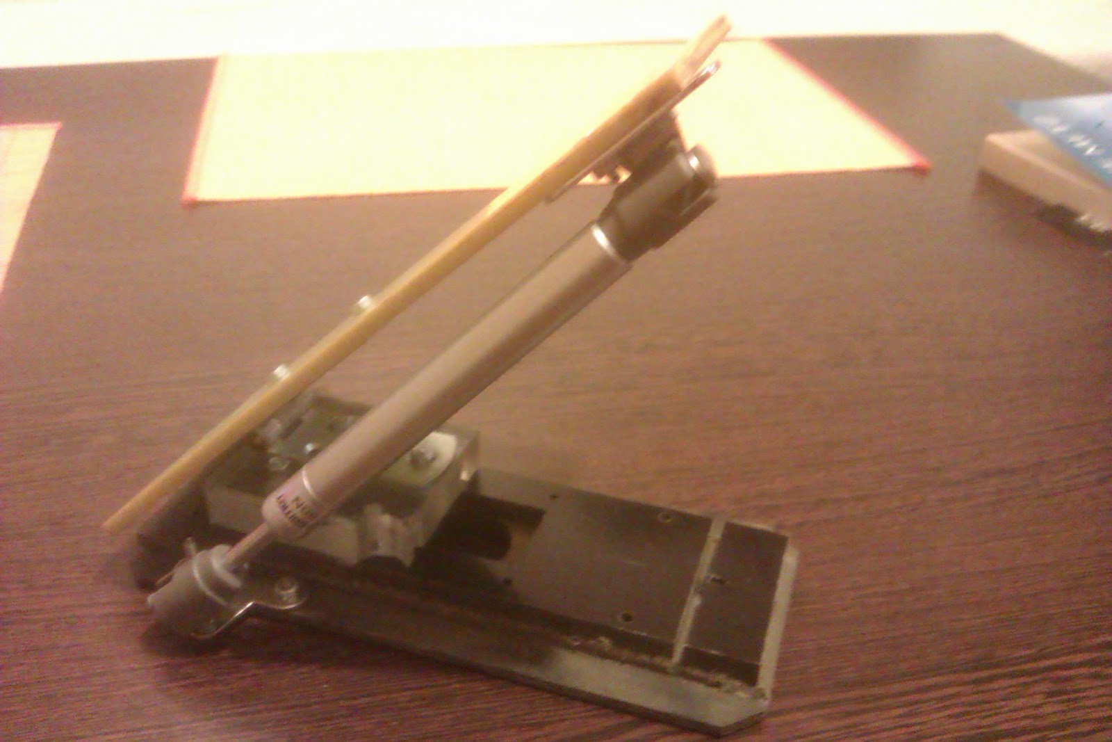
Now, I mentioned earlyer that I also want to have speed control.
That is done with a regular 10K potentiometer and a rack and pinion set.
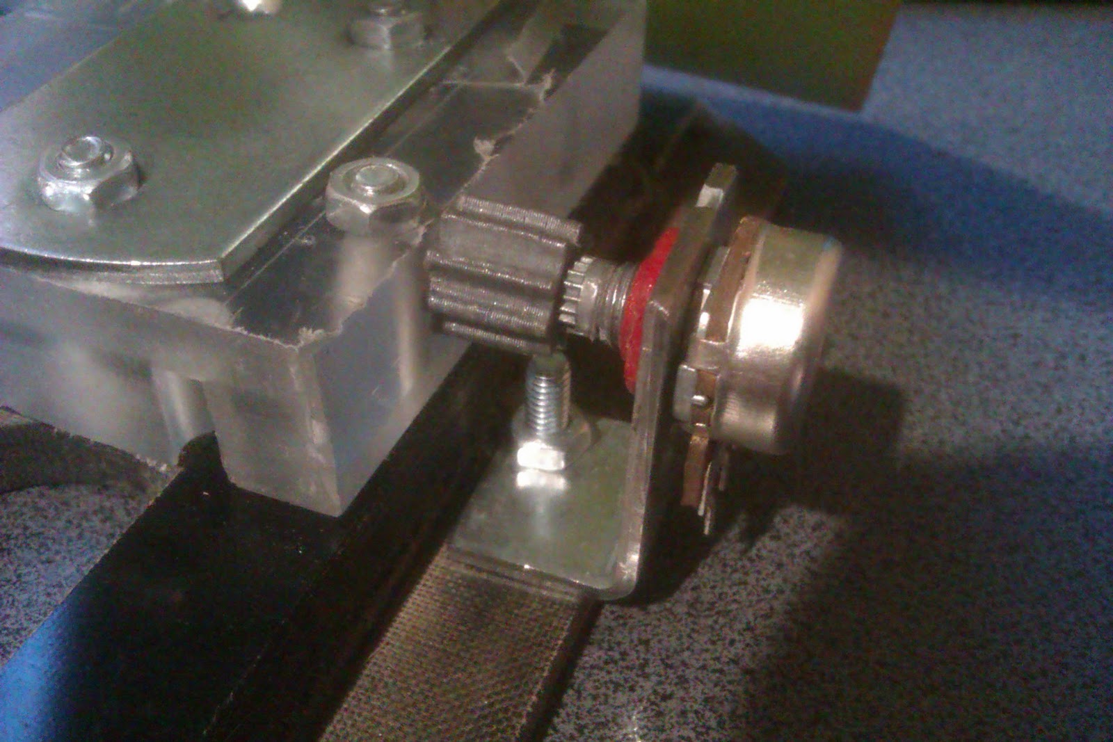
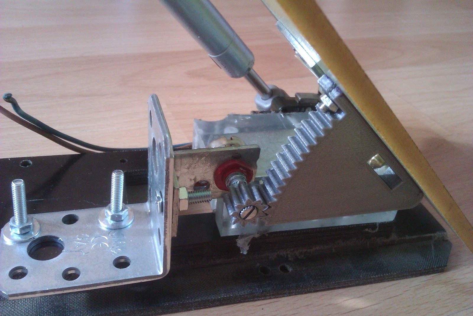
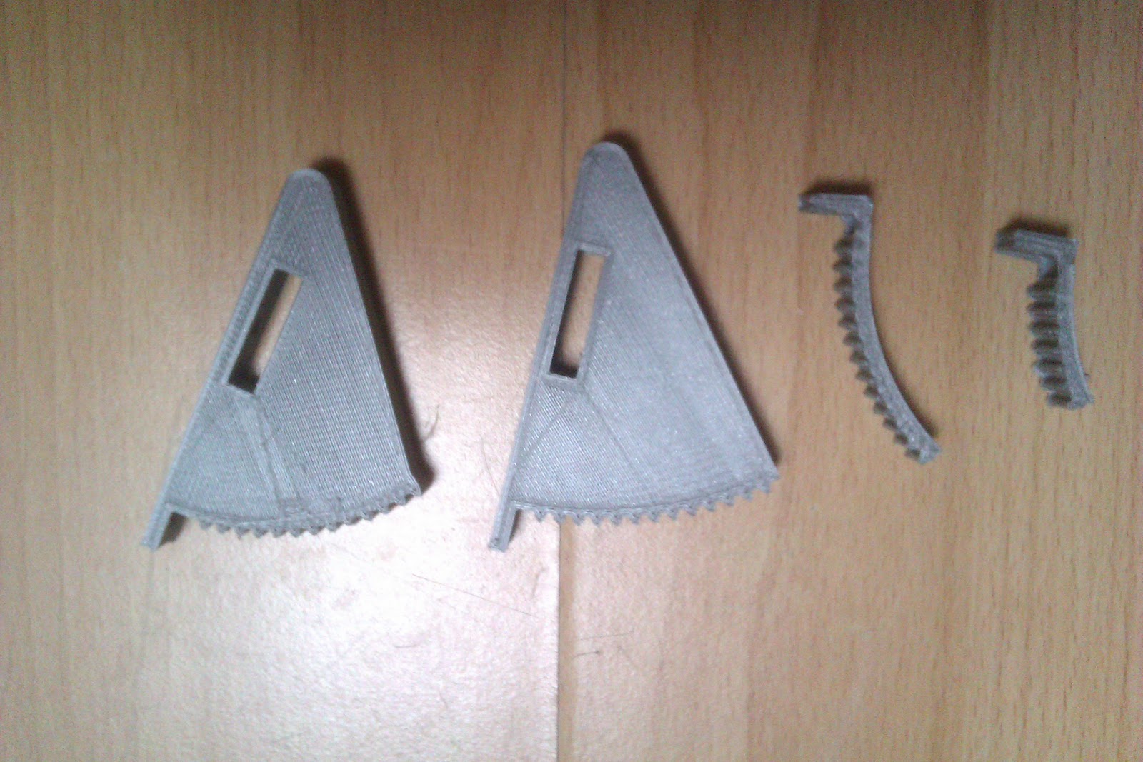
The parts were designed and printed by yours truly. Ok, only designed.. my 3D printer took care of the actual printing part.
The travel of the pedal actually matches to the 3-quarter-turns of the potentiometer. If you want to know how I did that....luck. Pure, dumb luck.
I thought I'd have to do some iterations before I got things to properly mesh (radius of the rack, number of teeth, pedal travel) but somehow I got it all in one go....
Or maybe not...
Keeping count of things
120...121...122...130... Obviously, it's not an improvement to hand winding if there isn't a way to keep track of your turns.
That shouldn't be too hard. The whole jig is already controlled by an Arduino, and it still has a lot of free pins. So let's use them.
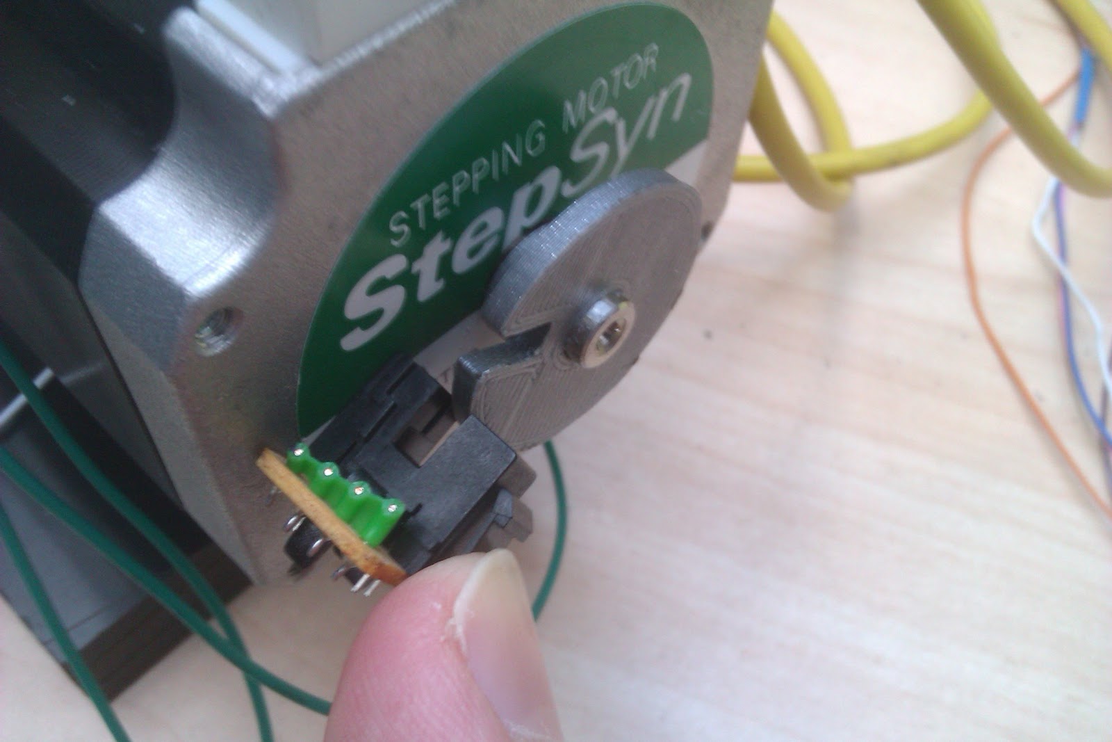
And since the motor happens to have an extended shaft out the back side, why not stick an infrared light barrier and a small wheel with a slot in it, on the shaft?
When the motor makes a full turn, it lets some light pass, the Arduino increments a counter on a display....Perfect!

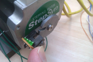
The wheel was 3D printed and you can find the STL and Solidworks files for it right here.
Putting all of it together
I had to build some kind of stand, for the motor. Once again I used some 15mm black resin impregnated fibre material and some 15mm thick polycarbonate scraps that I had.
The stepper was bolted to the frame with M4 screws.


When the motor makes a full turn, it lets some light pass, the Arduino increments a counter on a display....Perfect!
The wheel was 3D printed and you can find the STL and Solidworks files for it right here.
Putting all of it together
I had to build some kind of stand, for the motor. Once again I used some 15mm black resin impregnated fibre material and some 15mm thick polycarbonate scraps that I had.
The stepper was bolted to the frame with M4 screws.
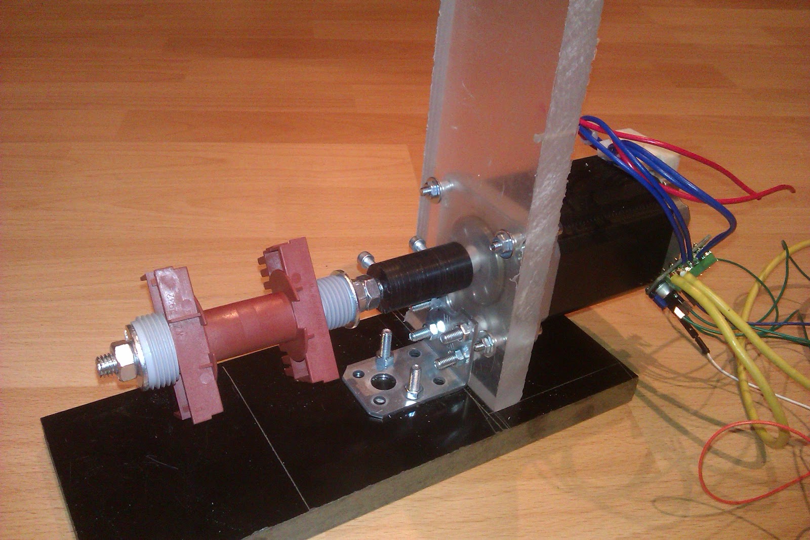

It may not look like much, but the whole frame, once everything was tightened down is verry sturdy and can take quite a beating from that stepper.
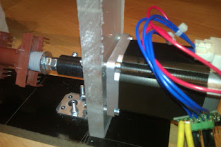
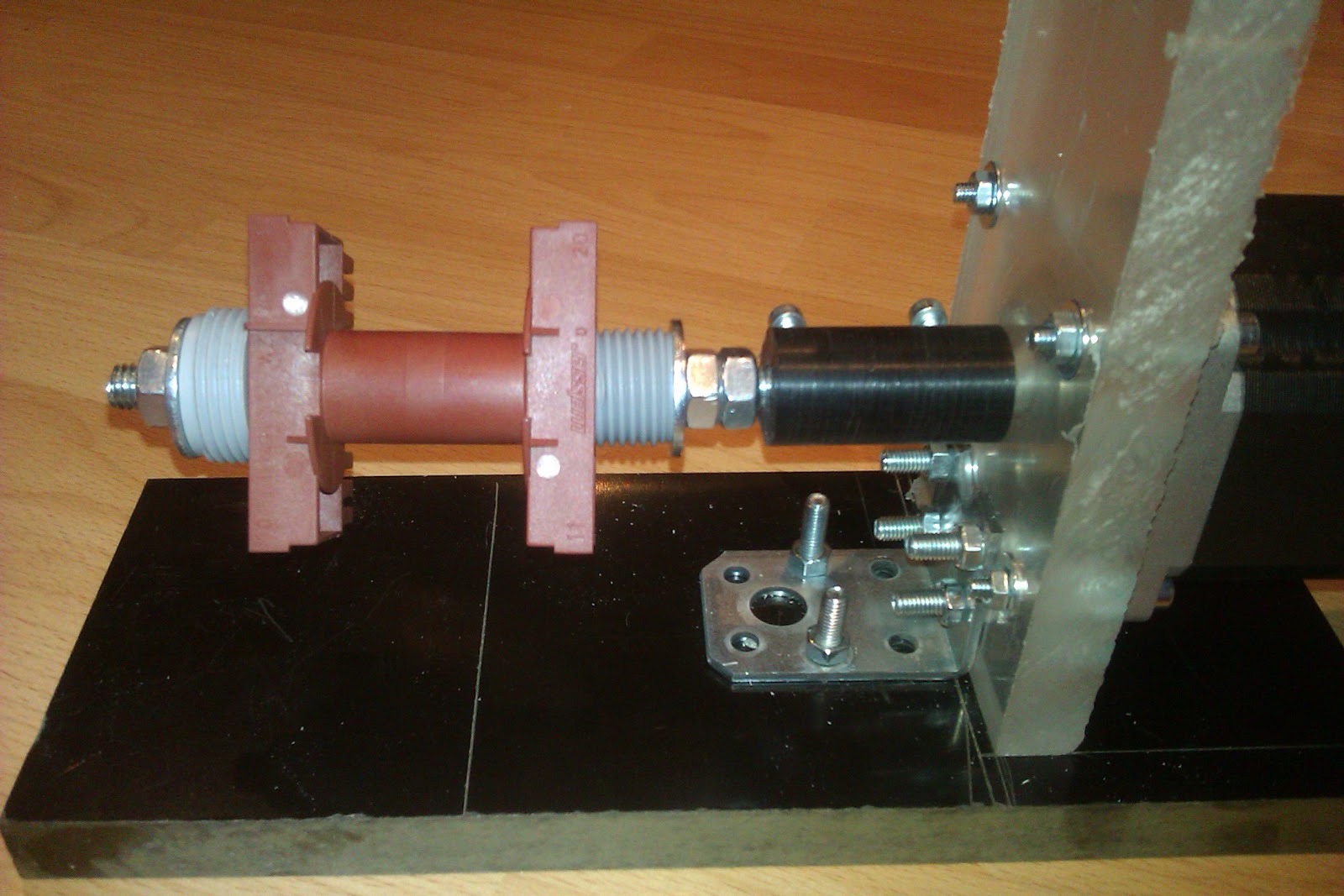
The black cylindrical thing is a home-made shaft coupler. I had some black delrin around that I bore on either side, to allow the 6.35 mm stepper shaft to couple to some M8 threaded rod. To keep the shafts from turning inside the coupler, I drilled two 6mm holes in the side of the shaft coupler then put in some brass inserts. Two M4 screws go into the inserts, locking the shafts to the coupler.
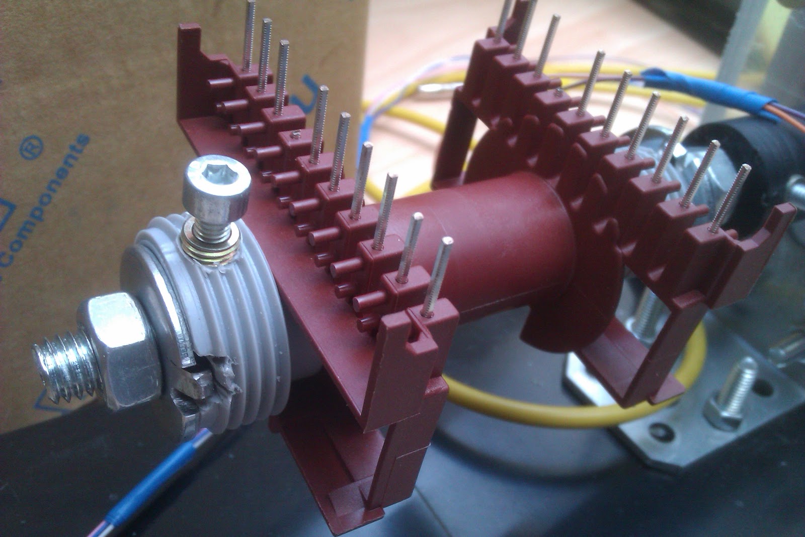
On the threaded rod I put some nuts as spacers and some Gardena hose adapters of some sort (the grey plastic things), that just happened to be the right shape to keep the ETD49 bobbin in place.

Sharing is caring
All the files for this build can be found on my GitHub page. These include the code for the Arduino, the SolidWorks and STL files for the optical rotary thingy and whatever else I may find useful to throw in there.
As always, you can enjoy the full splendor of crappy quality pictures of the build here.


0 comments:
Post a Comment