Yeah, I know. Weird, right? I know it’s not
what you’d expect, but hey… I felt inspired.
For those
that don’t know me, I have a bit of a
pencil fetish, and also I haven’t seen a review of these from an engineer, so I
figured I might just as well. And just as a mention, no, I don’t use the
pencils for “art” purposes. I can’t draw a picture to save my life, but what I do
draw with the pencils are mainly schematics, make some annotations or draw up
mechanical stuff.
But, before I start, I’ll make the
disclaimer that these pens were bought with my own money. I’m not affiliated
with any company selling these pencils. It’s just me, trying to put down my
thoughts, likes and dislikes about these four models that I have.
And now,
let’s get down to it.

The pencils (from left to right) are:the Uni Kuru Toga Roulette (also 0.5mm), the well-known Rotring 800 (0.5mm lead), the Rotring 600 (0.7mm) Black, though I'd normally expect it to be longer than any other pen... cough cough... and the Pentel Graphgear 1000 (0.9mm).
First off is
the Rotrings. Now I should just start by saying that both pencils are my favorite. The design is simple and elegant but has a very technical
aspect to it. The whole body is made from nickel plated brass so they have quite some heft to'em.
And you can feel this when you pick one up. For some people this might be a
turn-off, but personally, this is one of the reasons I like it.

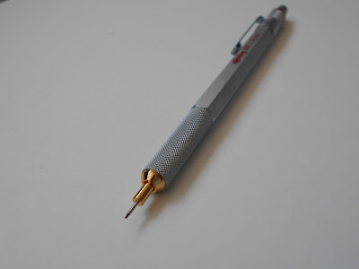


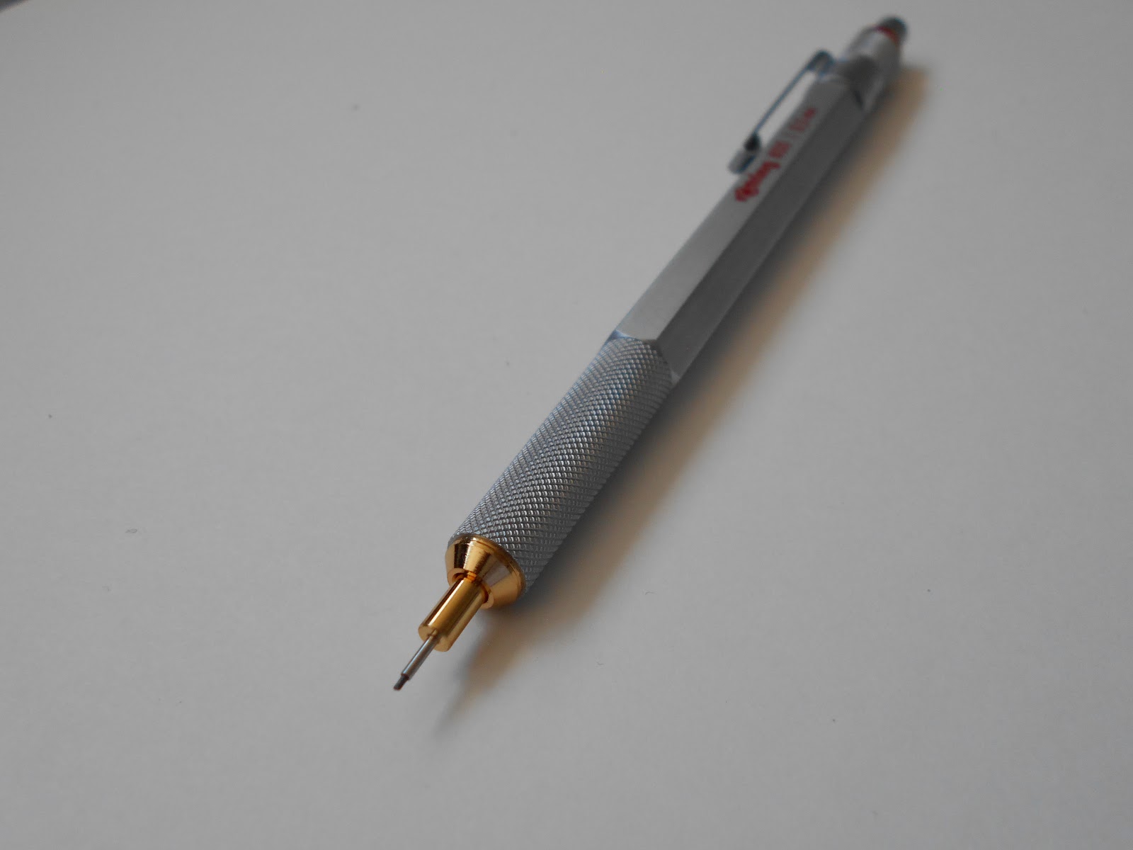

Despite the weight, they're well balanced and don't feel tip-heavy. The 800 model features a retractable tip so you take it with you
to work…to show it off to your fellow
engineers and make then jealous.
Aesthetics-wise,
the contrast between the bare brass accents and the dull nickel finish on the 800 is very nice and,
considering the money you pay for it (65 Euros), the guys at Rotring really
paid attention to the details. When you retract the tip, you can actually leave
the lead sticking out a bit and it still
won’t protrude out, something that
Pentel didn’t really get right.
The 600 one is also very pleasant looking, sporting a lead indicator and a black satin finish. This feels more rugged and bumpier and also makes it a pain to take proper photos of it.


The 600 one is also very pleasant looking, sporting a lead indicator and a black satin finish. This feels more rugged and bumpier and also makes it a pain to take proper photos of it.


When you look at the Pentel, you’re met by
a generous grip with rubber inserts and an overall nice looking design. Then as
you go up, to the clip …… NO!... Just
No!


There’s a gaping hole right under it,
like someone had his way with a dremel
tool. And that exposed plastic mechanism inside…..
Ok, I’d have
no problem with this, it still looks kind of nice, but considering the ~20 Euro
price on it, I’d have expected a different kind of locking mechanism that
doesn’t let you peek under its skirt.


It is
heavier towards the tip, which depending on your preference, it may not be a
good thing (I like it though)
Fancy-pantsy stuff aside, the pen itself is
really sturdy and nicely built The body is all metal and just like the Rotring,
it looks like it can survive a small nuclear blast. The model I have takes 0.9
or 1mm lead, but regardless of the size, the problem is the same…. you have the lead sticking out and you
retract the Pentel’s tip… but there’s still going to be some lead poking out.
Which, let’s face, it’s not the end of the world, unless your OCD kicks in. And
then you have to pull out the tip again,
depress the lead release thingy, push the lead back in, then retract the tip
again....sigh...
And speaking
of OCD, whenever I’m using it, if I rotate the pencil too much in my hand, the big metal clip
hits on my thumb and becomes somewhat of a nuisance. Therefore, I can’t really
rotate the pencil as much, so the lead gets lob-sided really fast.
But still, between these and the knurled
grip and the lead hardness indicator, it remains a fine instrument which
I love to use, despite the shortcomings (most of which are psychological).
The Uni pencil is the latest in my
collection and also the cheapest… something like 17 euros including shipping.
And unlike the Rotring and Pentel, it came with extra lead and erasers So thumbs up for Uni.


Design-wise, the grip is metal with fine knurling
on it, while the rest of the body is plastic, making for a nice overall look
and feel. Personally, I’d have liked all of it to be metal, but you take what
you can.
The tip doesn’t retract like on the other
two but that again, it’s already got a gimmick of its own: it rotates the
lead a bit, every time you touch the paper,
ensuring the wear on the tip isn’t lob-sided
And it
actually works quite well. At least for doing schematics and drawing small and
medium length lines.


It takes a
surprisingly light pressure to make the mechanism actuate and from the little
use it’s had, I think it’s a real nice
piece of engineering.
I’m curious about is how sturdy and durable the mechanism is, but only time will answer that question. The tip doesn’t flop around because of this. It’s firm when in contact with the paper and I can’t feel the actual movement of the lead, which is what you’d expect
I’m curious about is how sturdy and durable the mechanism is, but only time will answer that question. The tip doesn’t flop around because of this. It’s firm when in contact with the paper and I can’t feel the actual movement of the lead, which is what you’d expect
Of course,
no review would be complete without some true engineering work and some final opinions regarding the pens
Now, something that pops up almost always is tip movement. Most people say some pens have a tip that does the conga, while others say theirs is stiff as a coffin nail. Truth is, I'm curious what that actually means, in engineering terms. How much is too much movement?
Also, when you have something that's 0.7mm in diameter and 20 or 30 mm long, that's surely going to flex, no matter what. And some retractable tip pencils tend to have a real issue with this.
Also, when you have something that's 0.7mm in diameter and 20 or 30 mm long, that's surely going to flex, no matter what. And some retractable tip pencils tend to have a real issue with this.
So, I got out my trusty gauge and set to find out.
The set-up consists of this big hunk of square milled aluminium bracket to which I so professionally held down my pencils to measure the tip movement. Yeah, we don't need no stinkin' granite plate and toolmaker's vise.


I took some care to only put slight pressure on the tip, so as to get the measurement only for the free movement and not put additional pressure that would actually bend the tip. I succeeded, somewhat, but for a manual set-up like this, you can't really expect too muhch out of it.
And now, the results I got
Now for some fun facts that came out of using these pencils for a while.
The Pentel, which is the less used of the lot, due to it being a 1mm lead, is OK, but kind of awkward to hold. Also, that big hole in it kind of putts me off sometimes.
The Rotrings are great for everything, from drafting to writing and feel nice in the hand. The black version of the 600 that I have has some sharper knurlings and you can see that in most pictures online.
Probably due to the black coating or treatment it has. But still, it's on par with the 800.
Between these two, the 600 has a very satisfying "click" to it and the lead hardness indicator on it makes it stand out. That, and the black paint job. The 800 's mechanishm isn't that "clicky" to be honest, but the fit and finish.. well that more than makes up for it.
The Kuru Toga's hybrid style, part plastic and part metal gives it a nice look, but just knowing it's not completely metallic, kinda gets my nerd-juices in a tight spot. Still, I've used it and can say that as far as drafting goes, the roulette mechanism works, but for writing.. the pencil lead is gone in a flash. Full discolsure: I have bad handwriting and I mostly use cursive, so the mechanisn isn't really being put to good use here.
The knurlings on it are awesome and give it a unique look and for better or for worse, it's something I can tolerate having on my desk within arm's reach. Oh, and I think it's worth mentioning that the factory HB lead that comes with this one is a bit on the soft side, compared to regular HB from Rotring or Faber Castelle.
And speaking of soft, the eraser is also like this.... so now I know why it came with so many spare erasers.
As a final word, there's also some Rotring Rapidographs ISO that I recently bought and reconditioned. so expect some nice pcs for thse in the future. Oh, and I also got an old drafting (draughting?) kit......aaand a Leroy lettering kit... some of you know where this is going...

The set-up consists of this big hunk of square milled aluminium bracket to which I so professionally held down my pencils to measure the tip movement. Yeah, we don't need no stinkin' granite plate and toolmaker's vise.

I took some care to only put slight pressure on the tip, so as to get the measurement only for the free movement and not put additional pressure that would actually bend the tip. I succeeded, somewhat, but for a manual set-up like this, you can't really expect too muhch out of it.
And now, the results I got
- The Rotring 600, without the old in-out tip, registered 0.05 to 0.07 mm of movement
- The 800 on the other hand, with the retractable tip, got something like 0.08 to 0.1 mm
- The Pentel, the most beefy of the bunch tip-wise, got a 0.05 to 0.08 mm. Honestly, I would've expected even less movement, though most of it.
- As for the Uni Kuru Toga, the one that started this idea in the first place, the tip moves something like 0.15mm.
Like I said the method I tried out isn't fool-proof so take these numbers with a grain of salt. Also this is side-to-side movement. So when you're putting pressure on the pen, the travel is basically halved.
And even though the Uni Kuru Toga has the largest movement, I can't say it is something that you feel when writing or drawing.
Now for some fun facts that came out of using these pencils for a while.
The Pentel, which is the less used of the lot, due to it being a 1mm lead, is OK, but kind of awkward to hold. Also, that big hole in it kind of putts me off sometimes.
The Rotrings are great for everything, from drafting to writing and feel nice in the hand. The black version of the 600 that I have has some sharper knurlings and you can see that in most pictures online.
Probably due to the black coating or treatment it has. But still, it's on par with the 800.
Between these two, the 600 has a very satisfying "click" to it and the lead hardness indicator on it makes it stand out. That, and the black paint job. The 800 's mechanishm isn't that "clicky" to be honest, but the fit and finish.. well that more than makes up for it.
The Kuru Toga's hybrid style, part plastic and part metal gives it a nice look, but just knowing it's not completely metallic, kinda gets my nerd-juices in a tight spot. Still, I've used it and can say that as far as drafting goes, the roulette mechanism works, but for writing.. the pencil lead is gone in a flash. Full discolsure: I have bad handwriting and I mostly use cursive, so the mechanisn isn't really being put to good use here.
The knurlings on it are awesome and give it a unique look and for better or for worse, it's something I can tolerate having on my desk within arm's reach. Oh, and I think it's worth mentioning that the factory HB lead that comes with this one is a bit on the soft side, compared to regular HB from Rotring or Faber Castelle.
And speaking of soft, the eraser is also like this.... so now I know why it came with so many spare erasers.
As a final word, there's also some Rotring Rapidographs ISO that I recently bought and reconditioned. so expect some nice pcs for thse in the future. Oh, and I also got an old drafting (draughting?) kit......aaand a Leroy lettering kit... some of you know where this is going...


