Total Pageviews

Wednesday, June 14, 2017

My Hi-Fi Raspberry Pi DAC project. The Design Phase

    I'm in no way an audiophool audiophile, but I do like to listen to good music coming from a nice bit of quality engineered speaker and amp.
I've had a Sony CD player ( CDP-X303 ES ) for a while now and while it's working nice, it has a huge drawback.
I have to buy a truck load of CDs just so that I can listen to my favorite songs. I tend to have a variety of preferences, mostly based on my mood, that's why I tend to listen to anything from Michael Jackson to  Linkin Park and from Run DMC to Eminem. And anything in between.

     It's much more convenient to download ahem.... BUY my favorite tracks and store them on a drive and listen to them from some kind of network DAC. It's also easy on the mind to know that if a track has some kind of artefacts in it, (Sone CDs I bought have these) you just delete it and downl.... buy another. Unlike CDs, where you just have to live with the thought that something you paid money on  has random shitty, thunderous noises on it. 

PS: Don't buy the Michael Jackson CD albun "The Essential Michael Jackson" from Sony Music. You'll be trully regret it if you do. At least, I did.


A Networked DAC


    So, first of all, I need a board that links whatever DAC I'll make, to my LAN at home, so I can access the songs. And  it'd be nice to also play them.
   It'd be even better if I don't have to spin a whole board for this, so I'm thinking something along the lines of an Arduino or Raspberry Pi.

    I want to be able to play stuff like FLAC or WAV at something like 192 to 380 Kbps, 24 or 32 bits. Also, the few DACs that can handle these bit rates have an I2S (no, it's not a typo) interface, and conveniently enough, a few platforms have an I2S  bus available.
  One such platform is the Raspberry Pi. It's  cheap, has a ton of processing power and best of all, there are a lot of debians and ready-made software for it, covering almost anything you can think of.
  Another option would be the Odroid., which also has enough umph for the task at hand.

  For those cringing at the sound of using platforms like these for Hi-Fi, please keep your composure.  Your finely-tuned ears can't really tell the difference between a 1000 $ DAC and an embedded platform with a good DAC on it (except if the latter is poorly designed). 
  Now, having said this, please excuse me while I go put on my flame suit.

    My decision went in favor of the Raspberry Pi platform just because I happened to have one around.

A quick search for a Raspberry debian that can handle all you music via a network interface will produce the following results:

 - Volumio
 - Rune Audio
 - Etc.

    There are a lot of web players out there that do  the same thing. My personal choice was Volumio. Why did I choose this over the others I hear you ask ? Well, because this was the first result that popped up on Google.

Which one... which..one... Hmm...

    So, having solved the networking part, now all I need is a DAC that can do everything I want i.e. up to 382 Kbps at 32 bits.
A friend of mine did a similar project and he used the PCM5242 from Texas Instruments. It has a very impressive spec sheet, both in performance and in size. But the size is mostly due to its internal DSP. Yep, this DAC also has an  mini DSP inside. Wicked! That opens up a whole new world of opportunities.

Where's the rest of it?

    Anyone looking at the datasheet for this can plainly see the banner on the front page, where it says it has  a DSP inside it. But if you go on further, you start  to see that the datasheet is incomplete. It's missing some of the data on the DSP registers. Bummer. Plus, if you want to program it via an interface, you need TI's Pure Path Studio software...which can not be downloaded from anywhere. You have to send the guys at TI a mail with a request for it.

    Also, take note that there are a few commercial Raspberry shields out there that have the PCM5242. These claim it has a DSP inside  it, which is correct. Unfortunately, if you want to use it or program it, or do anything with it, other than just convert bits to sound, you're on your own. You basically have to create your own library for the PCM's DSP so you configure every bit of it.

    But let's not let this small drawback keep us from implementing what would be a very capable DAC
  I'm going to build one to see how it sounds and how it behaves and if I like it, I'm going to design another version where I try to use the internal DSP and actually put the whole thing to use.

Actually designing stuff

    Ok, so let's see how we're going to do this.
First thing's first: a normal I2S interface uses 4 wires.
 - A master clock, to time the whole thing - MCLK or SCK;
 - A bit-rate clock, BCK, that tells the DAC what bitrate the song is being played at, i.e. you sampling frequency;
 - The data line, DIN
 -  And a signaling line  - LRCK - to tell the DAC which frame of  data is for the right channel and which is for the left one.


Fig.1  I2S Bus with all 4 signals.BCK is derived from the MCK


Fig.2  I2S Bus implementing only 3 signals. MCK is 
internally reconstructed from the BCK

    Normally, the master clock would have to be set so that it is a multiple of the BCK. This means that with most network  DACs (I'm talking about the system as a whole, not the DAC chip itself) you need to have an external clock feeding the DAC directly, or an interface IC, (bridging something like USB - I2S) when an interface conversion is necessary. This is kind of cumbersome and adds a lot of parts to your BOM.
  If you are curious, you can have a look at XMOS's line-up of chips. There are some that go up to 192 k.

    But the PCM5242 only needs one clock - the BCK. It can take this and rebuild the master clock with an internal PLL, thus saving a lot of board space and simplifying the design.

   The 5242 can work either in Hardware mode, or Software mode.
 Hardware mode is kind of a stand-alone thing. You just feed it 1s and 0s from an I2S bus, then it converts them to sound. Easy. You also have some pins with which to control signal attenuation, and that's about it. I'm over-simplifying, but you get the point.

    Software mode is where the magic really happens. You still use the I2S bus, but you can also do soft muting on the DAC, you can control the volume in much finer steps, set PLL frequencies, write internal registers and also, my favorite, control the DSP. All this through an I2C or SPI interface. Your choice. Or, rather my choice, to be exact.

  The prototype is going to just run in HW mode. I don't want to deal with writing any internal registers and doing power ON/OFF sequences and stuff like that. At least, not just yet. I just want to see it work....or to be more precise, to hear it work.


Down to the nitty-gritty


    Ok, so having settled on hooking the DAC so it works in Hardware Mode, what other egineering stuff do we need, to make this thing work?

    My Sony amp has 1 Vpp inputs, but from what I've seen, it can tolerate higher peak-to-peak voltages. Up to 4 or 5 Vpp. I actually scoped a Sony 339ES CD player and got as much as 7Vpp.
 But for safety's sake, let's choose a maximum output voltage of 2 Vpp for the DAC hat.

  The DAC itself can output either 4.2 Vpp or 2.1 Vpp levels. So, let's go with the 2.1 Vpp.
Now, I'm kind of weary about powering the amp's input directly from the DAC, so  I want to put a buffer between them.
 Because I'm lazy,  and don't want to mess around with op-amps possibly oscillating like crazy, I'm going to go with the TPA6120A2 audio amp as the buffer. That's the one in the DAC's data sheet.

  Thus, the final output will have a level of about 4 Vpp (the amp's minimum gain is x2) but we can solve that with some extra attenuation from the DAC. For this, you just implement the table below so that your signal has the needed level.


Analog and digital power supplies design

3.3V PSUs

    The DAC needs both an analog power supply and a digital one, both 3.3V. This isn't such a big deal. But I can sure as hell try and make one out of it.

    One can easily fit a small SMPS or two on a Pi hat. The problem is however the noise these will generate. Ok, this, and the fact that some audiophiles will cringe at hearing the words "SMPS" and "Hi-Fi" in the same sentence.
    I want everything to be as clean as possible, noise wise, so my solution was to split the power supply from the main DAC board. Not only that, I went a step further and split the analog and digital supply, each having its own board.

    Having this configuration however can be more detrimental than helpful. One might be tempted to think that a current's return path would be that of least resistance to ground. And that is correct.. But where that ground is, that can be a bit tricky to find.
  In the set-up I proposed, the ground is not the one on the DAC hat i.e. the PCM's GND connections. It's the one way over on the PSU. So, the actual path would be DAC → about 5 cm of wires (2 inches for the non-MKS lovers) → PSU GND
With such a large loop area,  it's an open invitation to a whole lot of noise pick up, no matter how quiet the actual PSU is.

 I tried to mitigate this by having the PSUs regulate down to 5V for the PCM's power rails then have an additional LDO on the Pi hat itself, to do the rest of the work down to 3.3V. This  (I'm hoping) will "bring back" the GND return path to the hat. The current loop this set-up creates is the shortest possible.

To split o not to split, that is the question

   A recurring issue in this Analog-meets-Digital world appears: how to manage the digital and  analog ground planes for the DAC?
Having both an analog and a digital rail, how exactly do you route the grounds on the board so that you get the lowest possible EMI and the least amount of noise pick-up on you signal lines? Do you split them clear through the middle and place the DAC right on the center line? Or do yo just make on continuous plane?

  There are lots of articles  dealing with this exact issue, and depending on when it was written, you might get some diverging answers.
I have come across a couple of articles that explain the issue very well.
One is this article, which kind of gets you on the right path. If you need to go deeper down the rabbit hole, I recommend reading "Grounding in mixed-signal systems demystified", parts 1 and 2, from Texas Instruments.

  Following the general direction from these articles, I decided to only join my grounds under (or close to) the PCM DAC and exercise the right routing technique so that I have no analog signal wires crossing the digital ground or vice versa.
  Now, for this design, it's pretty easy to get things right, it's only going to be a two layer board and there are only 4 ICs and some passives on it, but for other designs, it can get messy when routing signal lines across the PCB, and keeping  the traces in their right ground plane can cause you some head aches

Cap selection


  No, I don't mean electrolytics. That's a discussion for another time.  I mean SMD ceramic caps. As in MLCC caps.


In this design, there are a few places where caps really matter, despite being used mostly for bypassing.

    The 3.3V regulators on the DAC board are LP2992 LDOs. Yes, Texas Instruments again. Now, these are advertised as having very low noise, and to achieve this, the datasheet recommends using some very low ESR caps on the input and output  and NP0 or C0G caps on the Bypass pin.
   My personal choice was to go with X7R caps for the 5V input and 3.3V output caps. The rest of the bulk capacitance will be on the PSU boards.
These have much lower ESR than electrolytics and behave much better under DC bias than X5R caps. Tantalums are on my naughty list and try to avoid them as much as possible. They don't take voltage spikes that well and their ESR isn't really that low.
    Also, the X7R material is less sensitive to changes in capacitance due to temperature and/or DC voltage (compared to X5R, that is).

  NP0 and C0G dielectrics are literally in a higher class than X7R / X5R. While one might use the latter in normal bypassing applications, the NP0/C0G can be used in filters, or for setting precise time constants. If you were to plot a frequency vs capacitance chart, you'd get pretty much a straight line from DC to about 10 MHz and a somewhat linear temperature coefficient.
This makes them very useful for, say.... some nice RC filters that go on the output of a DAC. And it just so happens that we have some of these between the DAC's differential output and the op-amp's input.

  You can find a lot of info about this on the net, so I won't bore you with too many details. You can check out this document I found in haste, while deciding which type of cap I should use. It's got graphs and tables in it , so it must be good.


Hardware Mode configuration pins


  Like I mentioned earlier, the PCM5242 can be used in Hardware Mode or in Software Mode, making it a very flexible design.


  First off, to put the DAC in Hardware mode, pins 24 and 23 need to be pulled low.
Now, there aren't many control options left. You can choose between a 2VRMS output or a 1VRMS output by making pin 21 Low or High, respectively (i.e. 1V out for AGNS high).

  I've already talked about the attenuation output pins so that's the important bits taken care of.
What's left is to set pin 16 Low, because we don't want any de-emphasis, and if you don't want to hear any hissing in your speakers when nothing's playing, then you'd want to set pin 1 Low.
There, that about covers it.


Schematic and PCB Layout

    If you're interested in building something similar or just want to have a look over the schematic, you can go to my GitHub  project page. There I have all the documents relating to this project. Feel free to download and/or use the desing as you might see fit.

  The laying out of the PCB went pretty much as I'd expect it for this simple design. Like I wrote, I opted to do the joined AGND and DGND sollution.
Unfortunately, because I wanted the bypass caps for the DAC as close to the pins as possible, I didn't have ena clear way to split the ground right beneath the DAC, so they're joined in two locations, either side of the DAC


     This may look weird, but I don't think it impacts the noise performance of this thing too much. But, if you believe otherwise and have more experience than me, then please leave a comment below, I'd really like to hear some nice explanations.


    So, basically, this is what I'm expecting to get from the PCB manufacturer. Except in black. It's going to be gorgeous.
Oh, and for those of you wondering what those holes on the bottom of the picture are.... wel,, I figured I'll just solder the audio output cable straight to the PCB. And to firmly hold the cable there and not put pressure on the solder joints, I figured I'd zip tie the cable to the PCB. A bit flakey? Maybe. But I  didn't want too many metal to metal interface between the output of the DAC and the input of my speaker amp. I may possibly be dellusional here, but hey... I like to experiment.

  The PSU layout also went snoothly and looking back, I could have squeezed both PSUs onto a single board or two smaller boards than the ones that came out. Next time I'll know better.


    Now, all that's left is to wait for the boards and parts to arrive.

  If you would like  to read on about how I put everything together, tested this and how it all turned out, the second part of this build is here.


Disclaimer: The stuff from TI I bought myself. I'm in no way affiliated with them. It just happened that they have the kind of parts I  needed


Tuesday, April 4, 2017

Transformer Coil Winding Jig

   
     If you can do it, then why not over-do it. At least that's what I did with this project. It started out small....just a simple motor, stick a bobbin on the end of it then wind away to you heart's content....Naaaa!

I need to control this...

Indeed, I do. And since  this will be a "hand winding" operation, it implies that both hands will be preoccupied with the....well, winding, of course. Therefore, who's going to control the motor? 
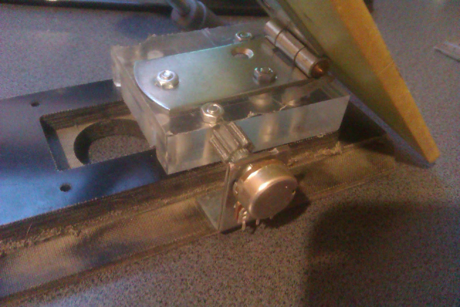
And since humans happen to have four limbs, an obvious candidate to fill in the position would be - a foot...by means of a pedal. Ergo, I need to make myself a foot pedal to properly control the motor. And not just an ON/OFF kind of control. No no no....I want speed control.


Choices... so many choices....


    Ok, so how about the heart of this thing? The motor. What kind of motor should I use? Well, a DC motor from an electric drill would have been enough. But like I said, why not overdo it. So, I had a Stepper motor driver available. It's an AMIS-30543 stepper motor driver that can do up to 3A per coil. Works for me.


   Now what kind of stepper? Some might think, "a NEMA17 stepper would do it". Not! 
From my pile of steppers, of course I went ans picked the biggest  most powerful stepper I had. It's a NEMA23, 3Nm  stepper motor. You might think it's overkill. But Since I do a lot of SMPS and high power stuff, there will come a time when some 0.7mm or 1mm magnet wire will have to be wound. And that requires a lot of torque at low speed. Yes, an electric drill ca provide that. I know, I know. I just don't want to use that.


Strange things are afoot


    Now for the control part - The pedal.
I initially though I could do the pedal with springs... big powerful springs. Of course, that didn't really pan out. The spring itself was OK, but the wire setup would either get snagged or the wire (guitar string wire) would stretch out and  wouldn't tension the spring properly.
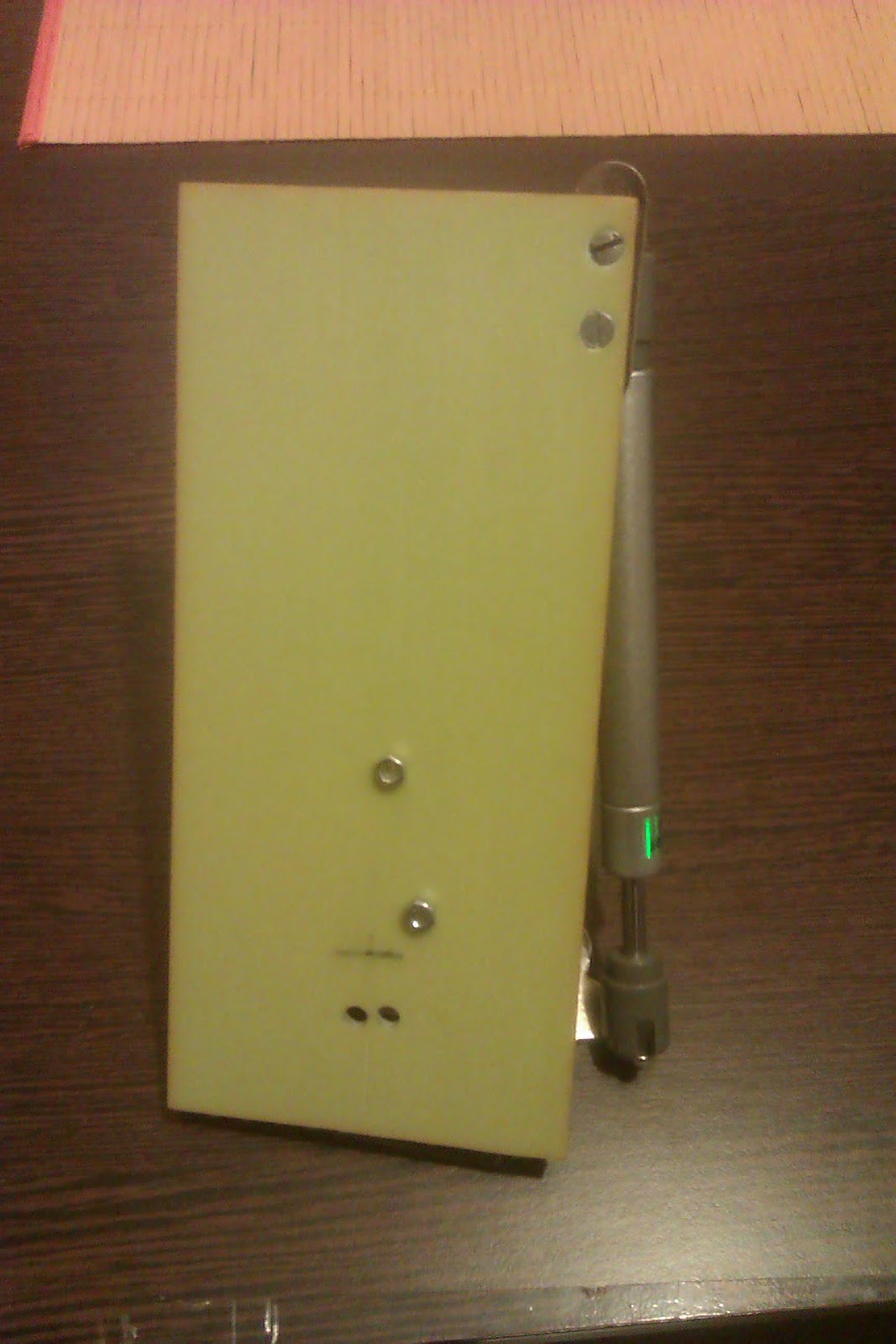
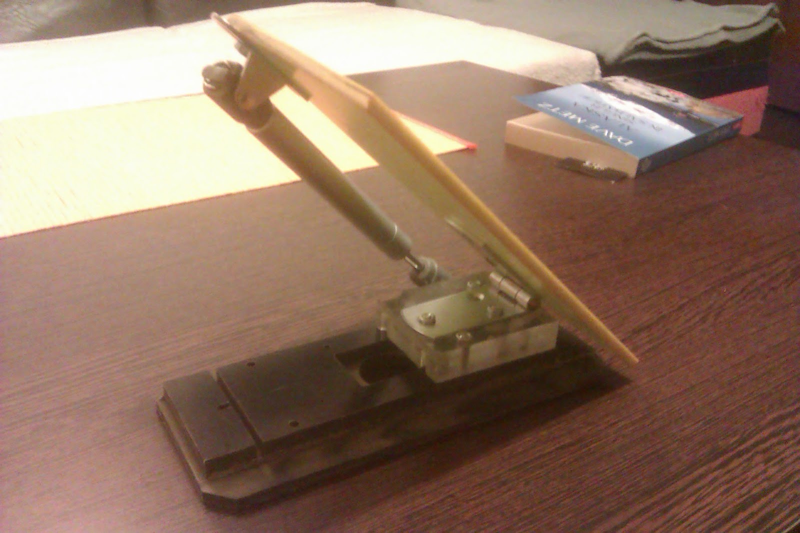
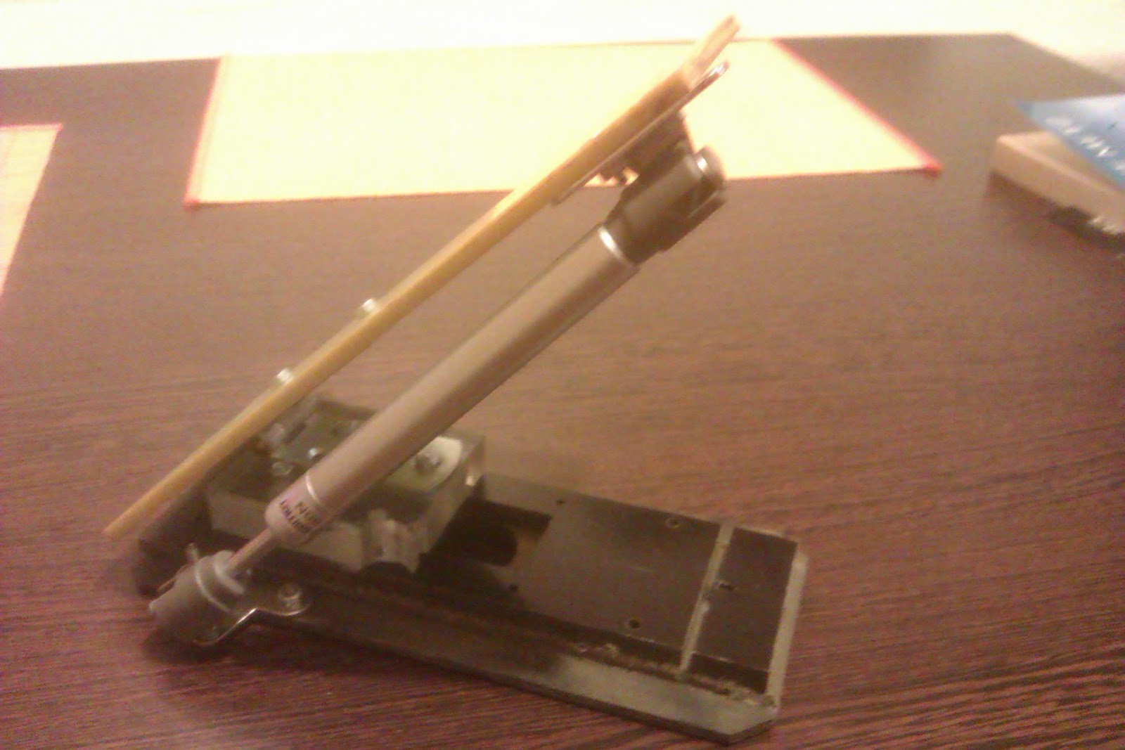
    But, being the engineer that I am, I often get inspiration from things around me. This time, it was a cupboard door hinge that used a telescope to help raise and lower the door. BINGO!

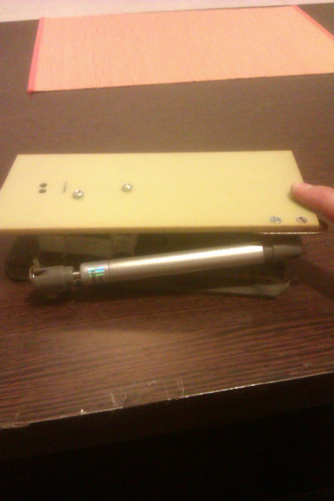
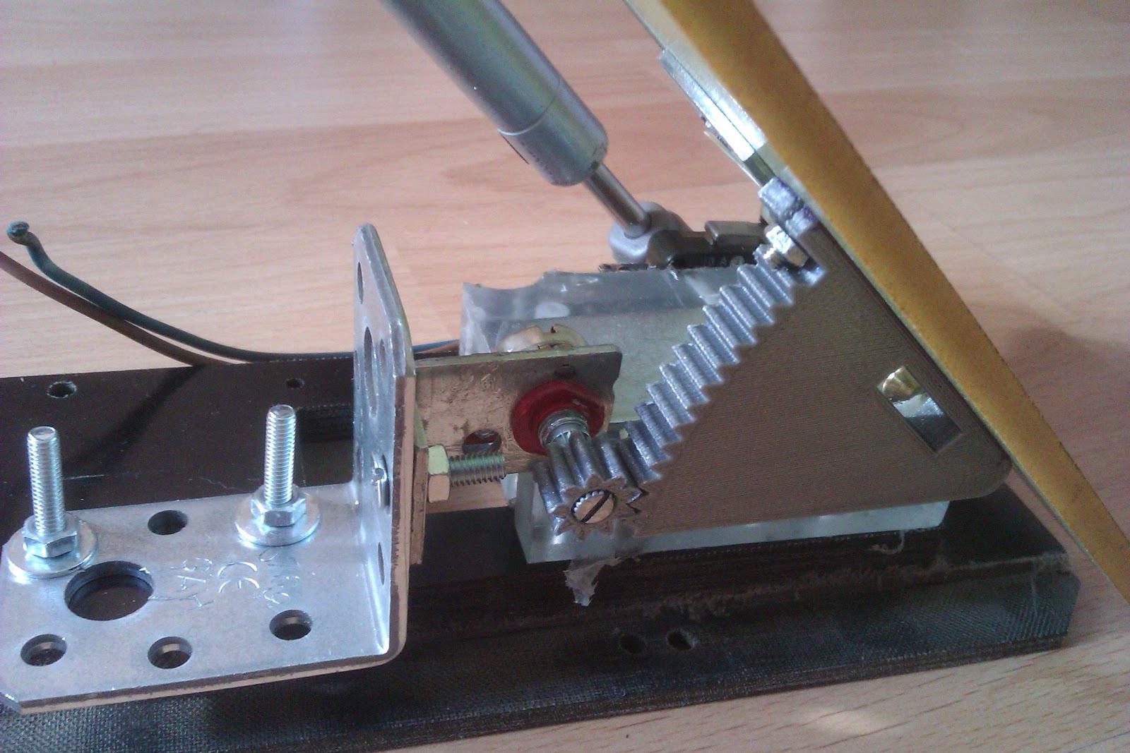
I went to the hardware store, bought two of those furniture telescope things, came home, threw away the spring and wire and mounted the new mechanism. And it worked. Brilliantly, I might add. It feels just right. The pressure i have to put on the piston feels just about right. And it's very smooth and controllable.


The two nuts sticking out  in the middle of the pedal will eventually get replaced by countersunk screw...eventually.

The base is made out of  15mm (590 thou, for those that still refuse to get with the program) thick resin impregnated fibres (cotton fibres, I think). Atop of that is a square polycarbonate piece, that holds the hinge. The pedal itself is made out of some kind of  5mm thick fibre-glass resin material.

If you're wondering about the routed edges and other stiff going on on the bottom black piece, well, don't They were already there. (I'm not that lucky as to posess a milling machine....yet)

Now, I mentioned earlyer that I also want to have speed control.
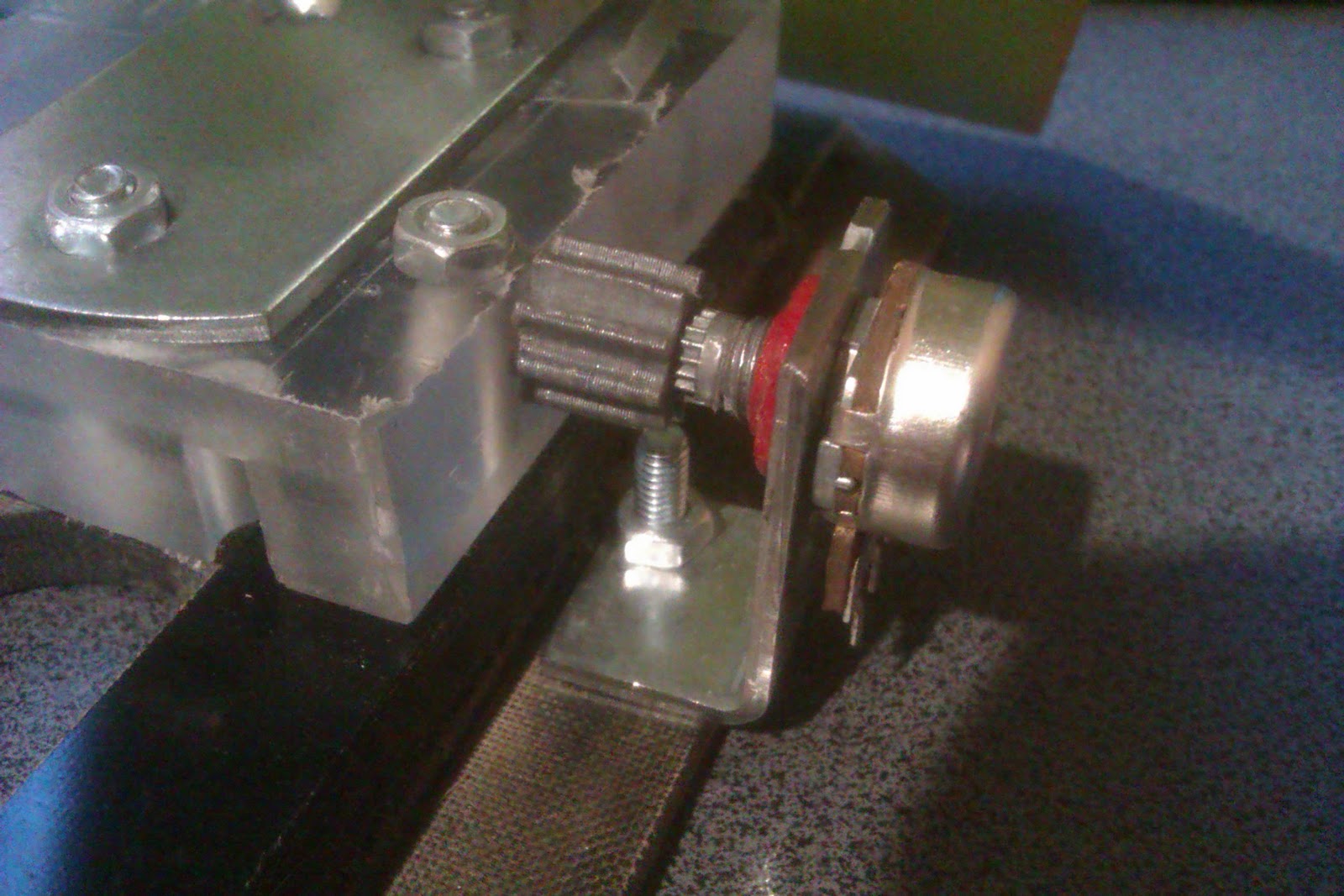
That is done with a regular 10K potentiometer and a rack and pinion set.


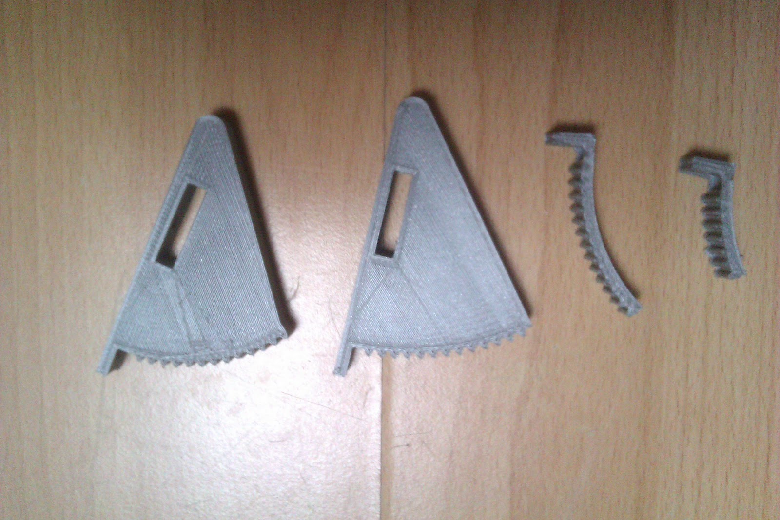
The parts were designed and printed by yours truly. Ok, only designed.. my 3D printer took care of the actual printing part.
 The travel of the pedal actually matches to the 3-quarter-turns of the potentiometer. If you want to know how I did that....luck. Pure, dumb luck.
I thought I'd have to do some iterations before I got things to properly mesh (radius of the rack, number of teeth, pedal travel) but somehow I got it all in one go....


Or maybe not...


Keeping count of things

120...121...122...130... Obviously, it's not an improvement to hand winding if there isn't a way to keep track of your turns.
That shouldn't be too hard. The whole jig is already controlled by an Arduino, and it still has a lot of free pins. So let's use them.
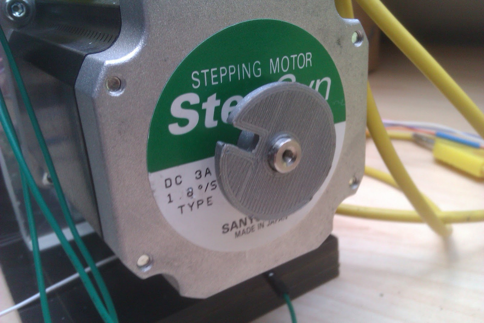
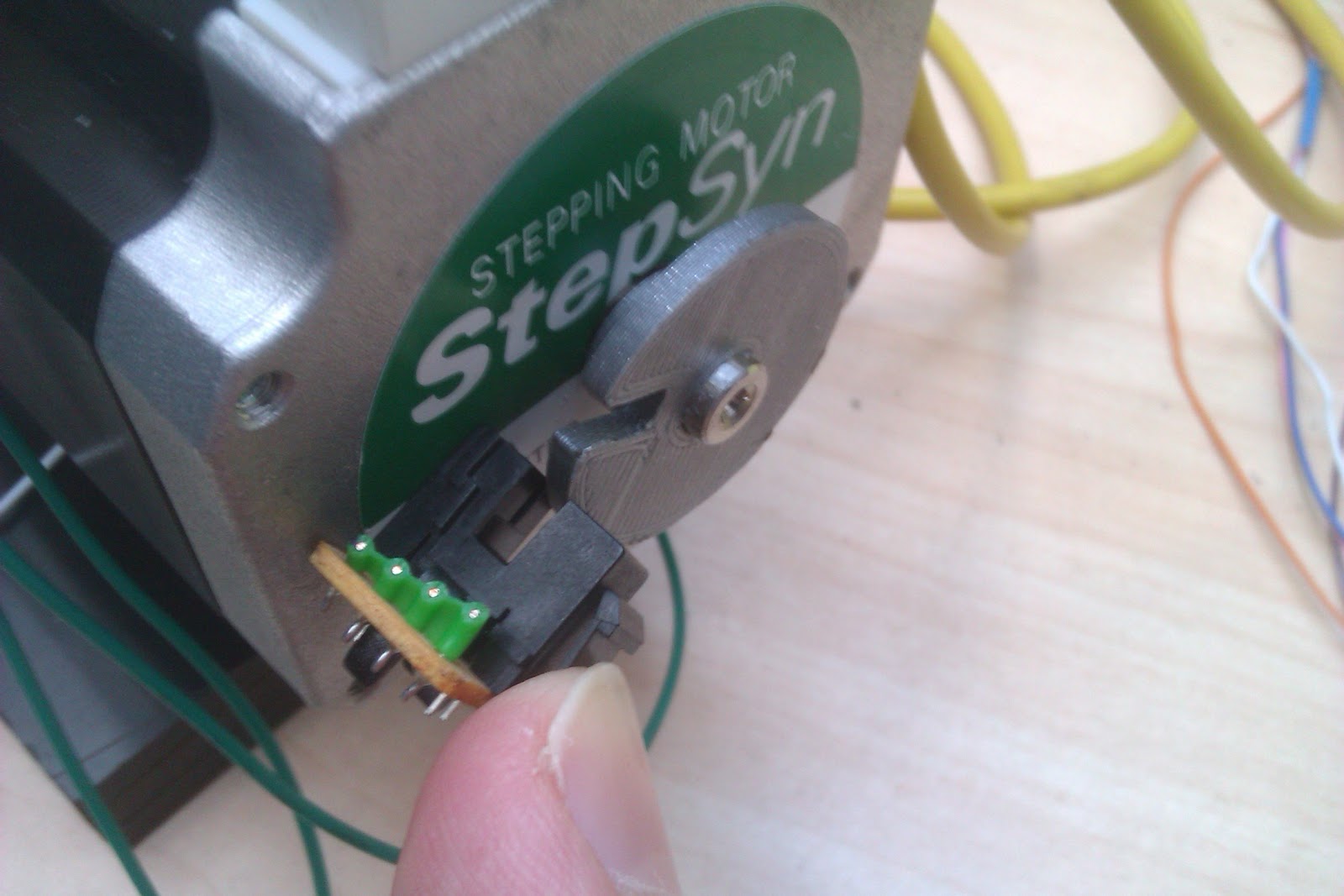
   And since the motor happens to have an extended shaft out the back side, why not stick an infrared light barrier and a small wheel with a slot in it, on the shaft?
 When the motor makes a full turn, it lets some light pass, the Arduino increments a counter on a display....Perfect!


The wheel was 3D printed and you can find the STL and Solidworks files for it right here.


Putting all of it together

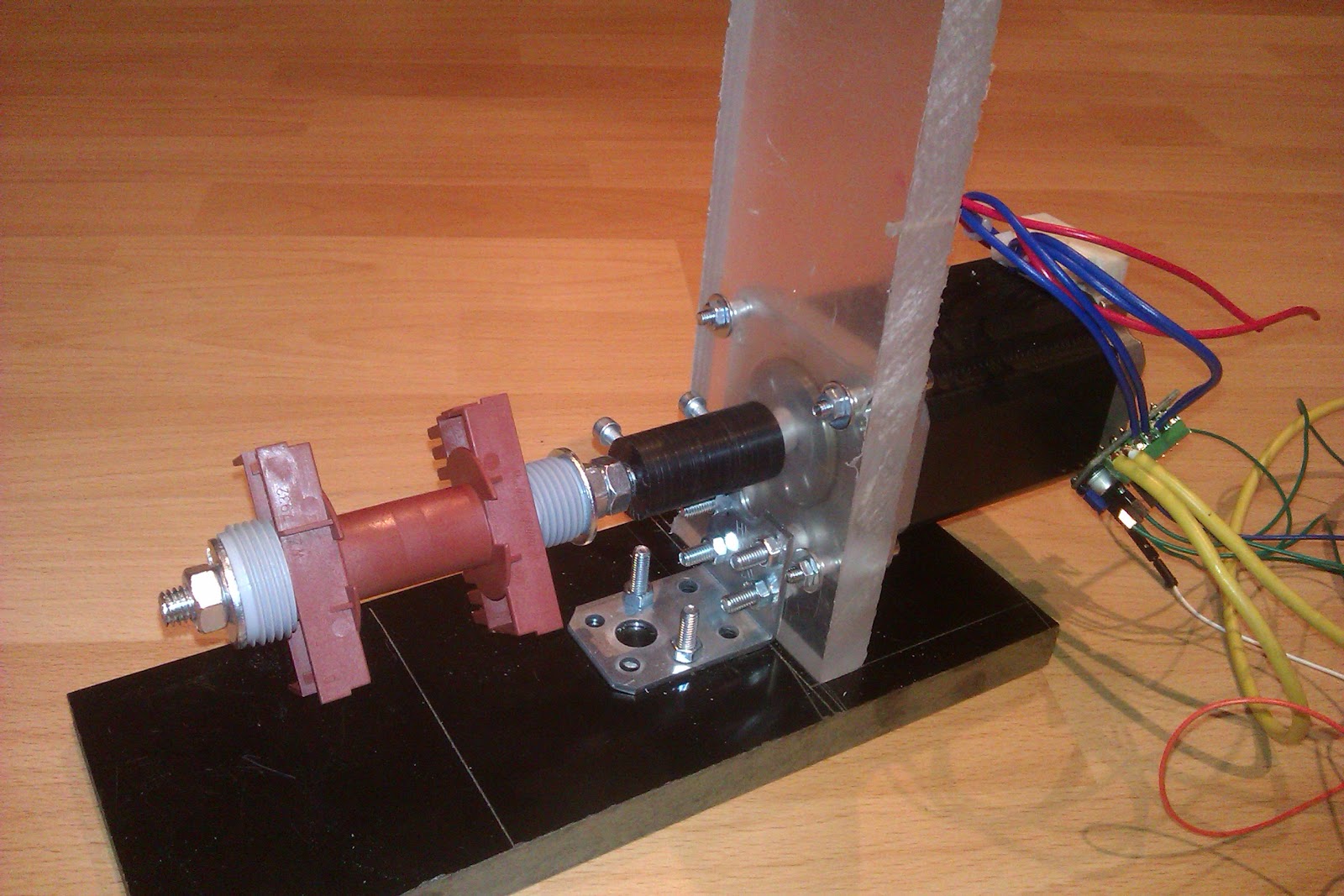
I had to build some kind of stand, for the motor. Once again I used some 15mm black resin impregnated fibre material  and some 15mm thick polycarbonate scraps that I had.

The stepper was bolted to the frame with M4 screws.


It may not look like much, but the whole frame, once everything was tightened down is verry sturdy and can take quite a beating from that stepper.

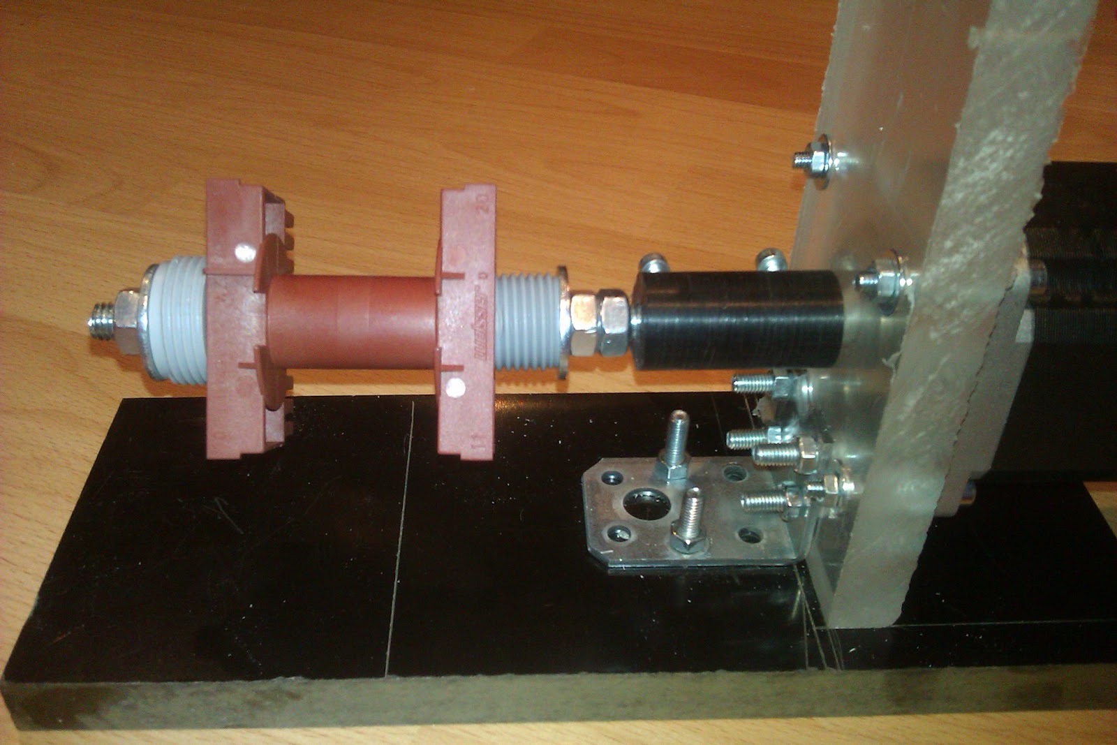
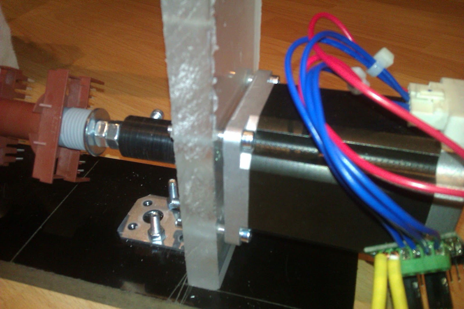
The black cylindrical thing is a home-made shaft coupler. I had some black delrin around that I bore on either side, to allow the 6.35 mm stepper shaft to couple to some M8 threaded rod. To keep the shafts from turning inside the coupler, I drilled  two 6mm holes in the side of the shaft coupler then put in some brass inserts. Two M4 screws go into the inserts, locking the shafts to the coupler.

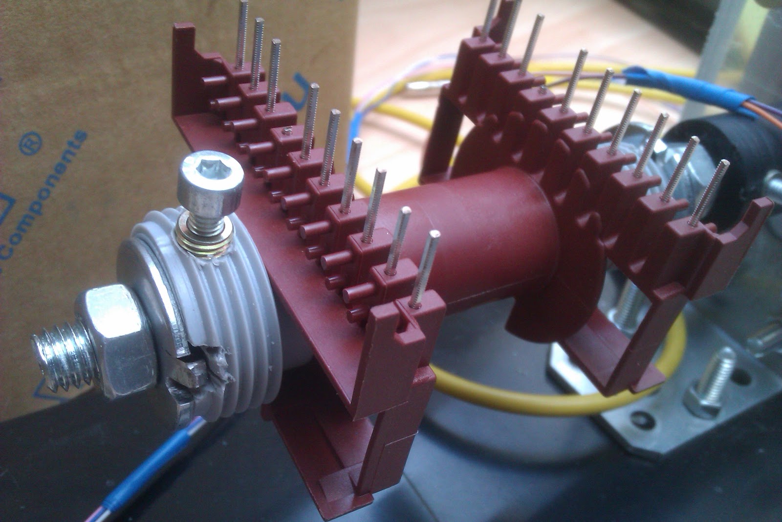
On the threaded rod I put some nuts as spacers and some Gardena hose adapters of some sort (the grey plastic things), that just happened to be the right shape to keep the ETD49 bobbin in place.


 I've also cut a slot in each of the grey plastic retainers and filed a mating pertrusion in the metal washers so that they wouldn't slip and turn ith the main stepper shaft. Of course, the plastic thingys will eventually be replaced with some proper 3D printed retainers, but who knows when that will be.


Sharing is caring

All the files for this build can be found on my GitHub page. These include the code for the Arduino, the SolidWorks and STL files for the optical rotary thingy and whatever else I may find useful to throw in there.
As always, you can enjoy the full splendor of crappy quality pictures of the build here.


Sunday, March 26, 2017

TwinTeeth Plus Build Log - Part 2

   
      This is an update on the TwinTeeth build that I'm doing. You can check out the previous part here.
   
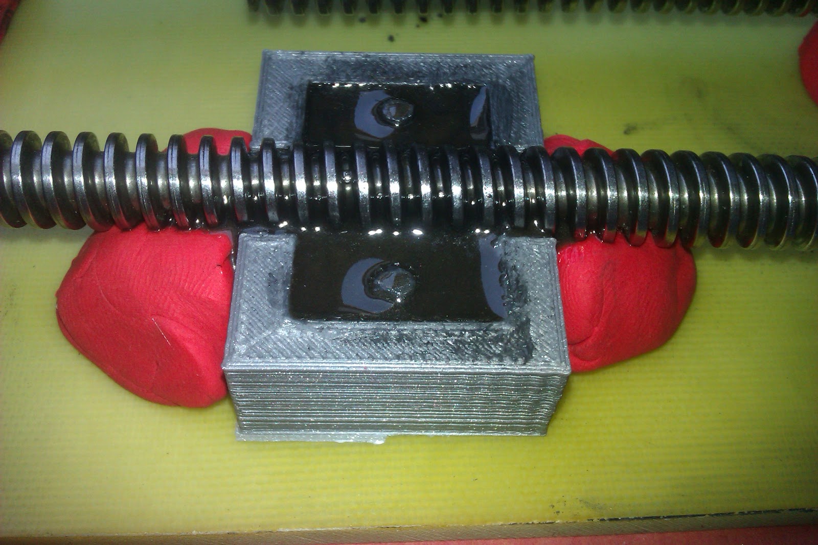
First, I have to admit that  molding your own ACME nuts is something far better than buying  them. All bought ones have an unsatisfactory amount of play, and when dealing with lasers, play and backlash is the bane of one's existence.

   Not being one to take anyone's word for granted, I initially bought some Nylon-MoS2 (Mylon-Molybdenum disulphide) ACME nuts, and though the person I talked to un the phone said it was done on a lathe, with an ACME tap, the end result is...well, shitty..


   They may look the part, but I measured up to 0.4 mm (15.8 thousandths for the imperial fanboys) slop in these bad boys. To say it's unacceptable  is a serious understatement.
Also, bronze ACME nuts won't do any better....Unless you do you own tapping on a lathe and get them to exactly fit the screw. But since I don't have a lathe....resin casting it is.

  I've tried several resins, from cheap and readily available ones to expensive cans of the stuff.

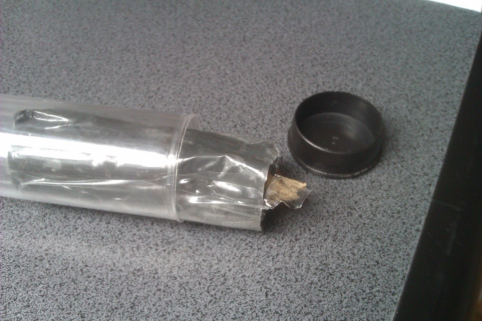
First off, I used this kind of resin:


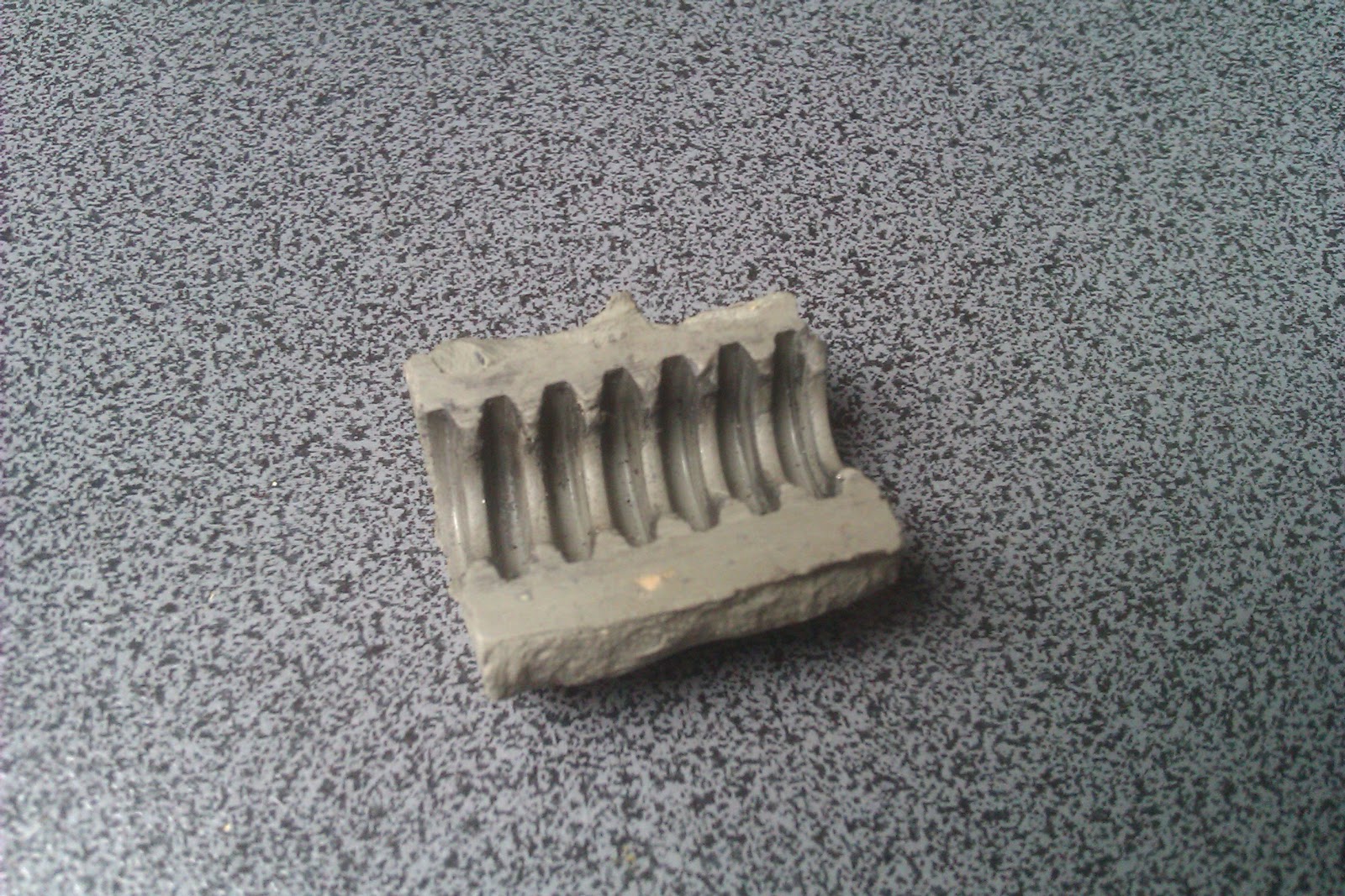
It's a  two-part putty-like resin. Just cut as much as you need and knead untill the colour is uniform. Unfortunately, although this cured rock-hard, it was very brittle and couldn't even take it out of the mold without flaking it or breaking it into several pieces. This was the biggest of them:


   Though it came out the way it did, I still could run the half-nut on the screw...by just holding it with my hand. Unfortunately, after  taking the nut from the bottom of the screw to the top, with only hand-pressure applied to the half-nut to engage the screw, I noticed that the ACME screw was stripping away material from the bearing surface of the half-nut. A lot of material. Needless to say, that's a big No-No.

So, I considered this alternative:


but after  seeing how the cured resin was just a bit on the stretchy side, I refused to give it any further  thought.

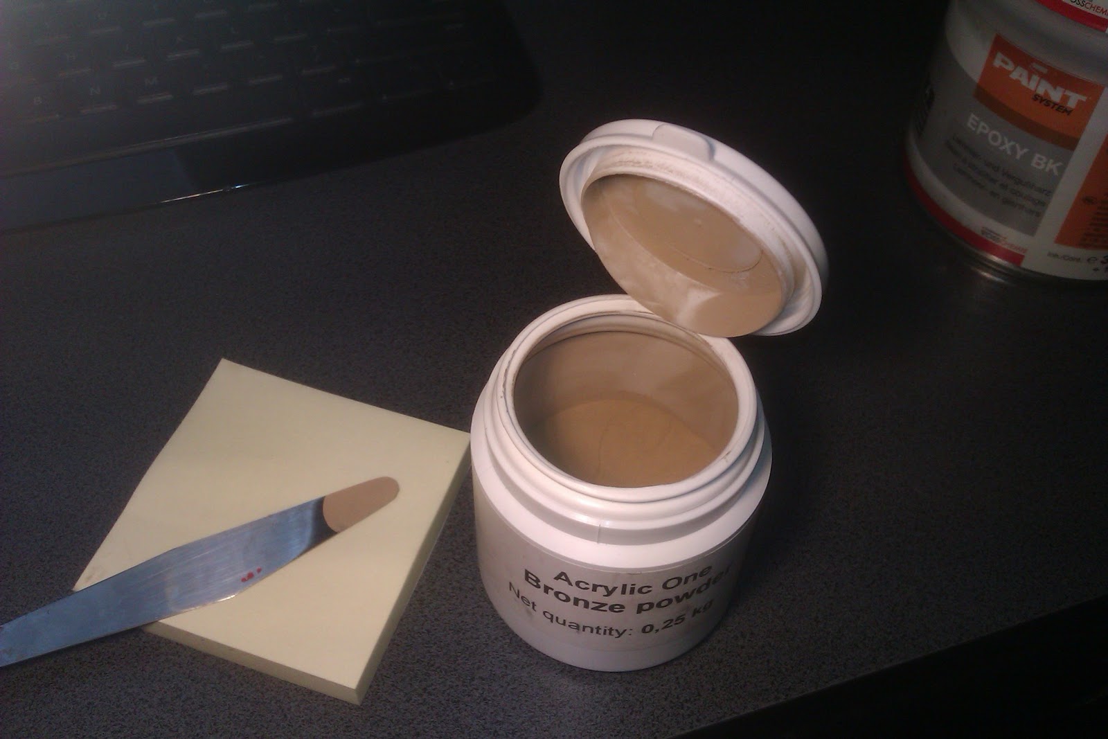
Finally, I bought some expensive cans of a two part resin and some bronze powder. 250 grams of the bronze powder were about 23 Euros and 500 grams of resin was aroud 30 Euros.


Now, just like in any cake recipe, it's essential to mix the right ammounts so that at the end, you aren't left crying over spilled....resin.

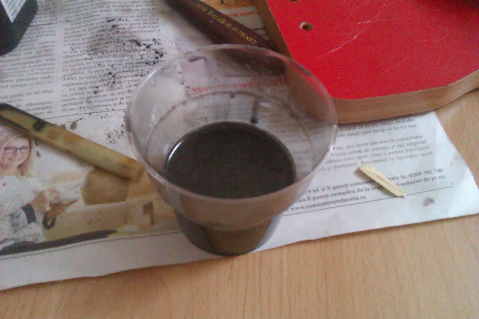
For the initial batch, I mixed 41 grams of A-part resin with 24 grams of B-part resin. I did this because first, the resin has a working time of up to 30 minutes and second, I read in a few places it's better to catalyze the resin first whenever you want to mix in metal powders.
Next, I mixed in about 7 grams of the bronze powder and about 1 gram of graphite powder.

Now, some of you keen-minded fellows may find that 41 g and 24 g means a whole lot of resin. And you'd be right of course. I mixed WAY more that I needed for 3 moulds. Something like 10 gr. of A resing and 6 gr. of B resin would have been sufficient. Oh wel... live and learn... and cry your heart out for all that wasted resin.


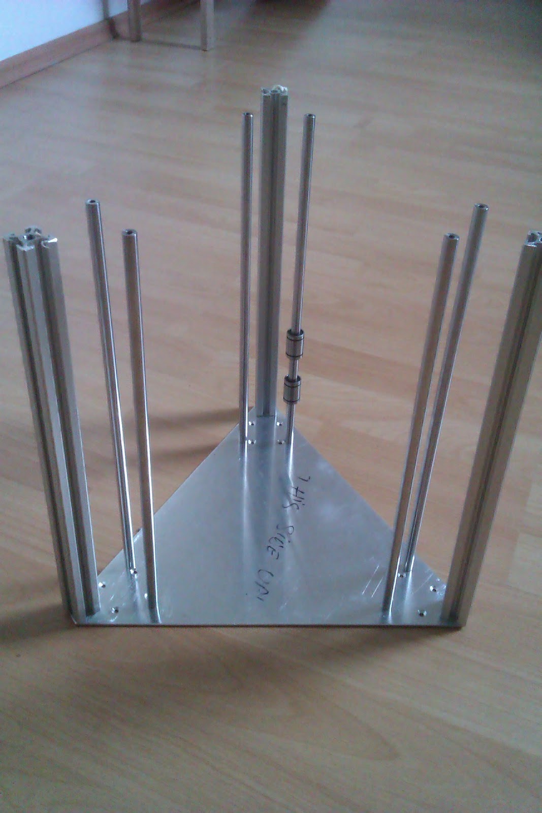
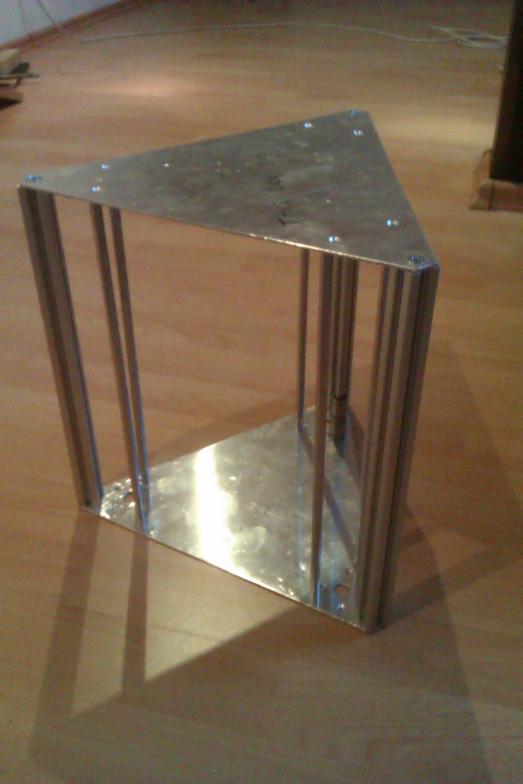
While the resin cured, I started putting together the rest of the frame.

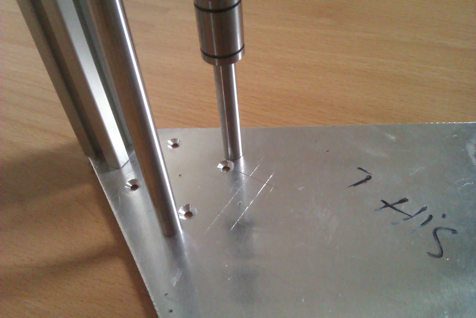
Apparently, the people I ordered the linear rods from didn't have a bottoming tap, so though the hole was 20mm deep, the threaded part was only 5mm deep. So I had to cut and grind 12 M4x16 screws to about 7 or 8 mm in length. Not really pleasant, but in a pinch, it did the job. The alternative was to order some M4x8 screws, which didn't really make  a lot of sense. Oh, and I just used a pair of pliers to get the screws lo length. Low-tech works every time.


The aluminium plates were all drilled and chamfered and once everything was tightened, the frame was really stiff. Remember, I used 2mm aluminium plate instead of 3mm, so I had some initial  worries regarding this.


I also bought some 6000ZZ bearings and fitted them to the lead screw supports. I kind of goofed up on the diameter of the hole for the bearing, but since I already had printed the three lead screw supports, I went DIY on it's ass and wrapped the outside of the bearings in some kapton tape. This made the bearings fit nice and snug. That's one way of solving it.


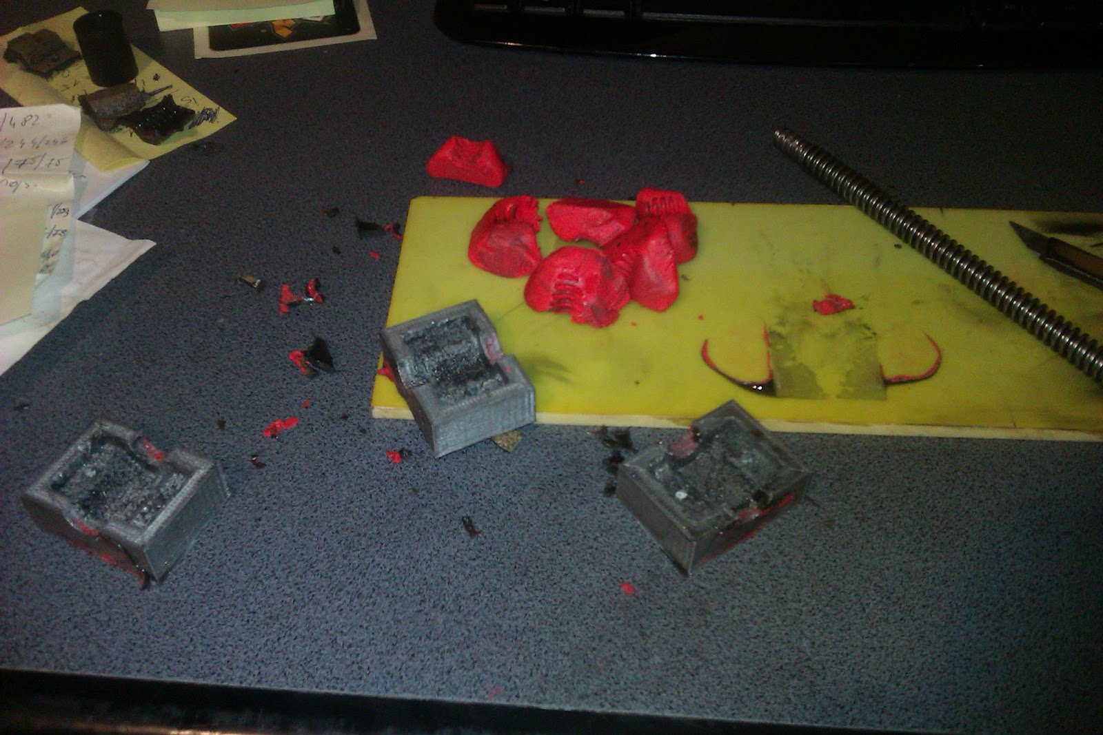
About 24 hours after the initial pour, I  took out the resin castings from the mould, and the results were....less than impressive:


    Because there were two stakes in the mould, for the mounting holes, the castings came out in pieces. But that was the least of my worries.... because the resin was really runny and thin, it allowed the bronze powder to sink to the bottom, instead of being uniformly dispersed into the resin, hence the gold colour on the back side of the castings. The graphite poder however seems to have been pretty well incorporated into the resin.

    So, for the next try, I'm going to have to do some experimenting.... I'm thinking one way would be to use less resin and add so much bronze powder, so that the resin will only serve to bond the bronze particles together, resulting in a casting that is mostly bronze powder (80 % bronze maybe?). 
Another option, just  add  something like 50 percent bronze powder to the resin mix and hope that wil thicken the resin enough to still be able to be poured but also not let the bronze settle to the bottom.

  However, despite this drawback, I did manage to try out two half-nuts on an ACME screw, and the result was pretty amazing.... Absolutely no slop in the nut. And though there was no bronze on the bearing surface of the half-nut, it moved very smoothly on the screw and without any (noticeable) resin material being stripped away by the screw, like with the first resin experiment I did.

    As a sidenote, a thing to consider when doing this is LUBRICATION of the moulds. Do not leave any part of the inside of the mould un-lubricated (is that a word?) It will be a nightmare to get the mould casting out. 
I smuthered the inside of my moulds in silicon grease and also dabed graphite powder onto the grease. I it hadn;t been for the two mounting posts in the mould, I think the castings would have came out in one piece.
   And if worse comes to pass, you can always print your moulds at about 10 Percent infill, allowing you to sacrifice the mould to take out the casting.

Sunday, January 8, 2017

Interstate Electronics Corporation SPG-800 Signal Generator Teardown


      Well. it turns out that Christmas came a bit later this year. Probably  one of the reindeers had a flat hoof, or something.


  OK, so I bought myself a signal generator for the measly sum of 70 Euros, including shipping. The guy I bought it from said the unit didn't work. No problem, I said to  myself. It'll make a nice organ donor for other projects. Probably filled with all kinds of goodness inside.....matched JFET pairs maybe.... a nice 10 MHz reference. I was drooling over it.

Now, let me tell you, when it came, I almost had a hernia. It's heavy as frig....about 20 Kilos worth of 2 DIN (I guess) rackable signal generator.

   So, I got the beast in the house (all the way up to the 5th floor and no elevator, mind you) and first thing I looked at was the fuse....which, of course, was nice and toasted. Before replacing it, I looked at the mains voltage selection switch. My optimism spiked when I saw it was set to 230 V AC. 
So, now, knowing that the main transformer and PSU inside it might be OK, I replaced the fuse, turned it on and....nothing, obviously.

   So, following the "Thow shall always measure voltages" rule, I got the DMM out and first thing I measured was the input to the transformer. It measured 0 V on its input.
Seeing as how the on/off switch was all gooey, I measured the voltage on its pins. Nothing as well. 
Ok, I'll bite.... I preceeded to desolder the wires from the switch, rummaged through my junk pile and found a suitable replacement then soldered back the wires on that one. 
   Because I didn't find the appropriate fuse size, I cobbled something with I could find. No pretty, but it did the job.


  Yes, apparently, it was just that simple. So, now that I had a working Signal generator, let's see what it can do. 
The first thing I noticed when turning it on was how loud the fan was. It sounded as if I had a tractor plowing right next to me.
  Unfortunately, I couldn't fin any FREE user's manual or service manual for this unit. There is on on eBay for sale, but as of writing this , it cost about 80 dollars including shipping. Needless to say, the guy selling it can just shove it, I ain't paying that much. I;m sensible for these kinds of things.

  Ok, so from playing around with the unit, it looks like it can do a frequency range from about 10 mHz all the way up to (what should be) 10 MHz. If it goes higher, I couldn't find the right combination of random key presses tht made it go beyond 10 MHz.
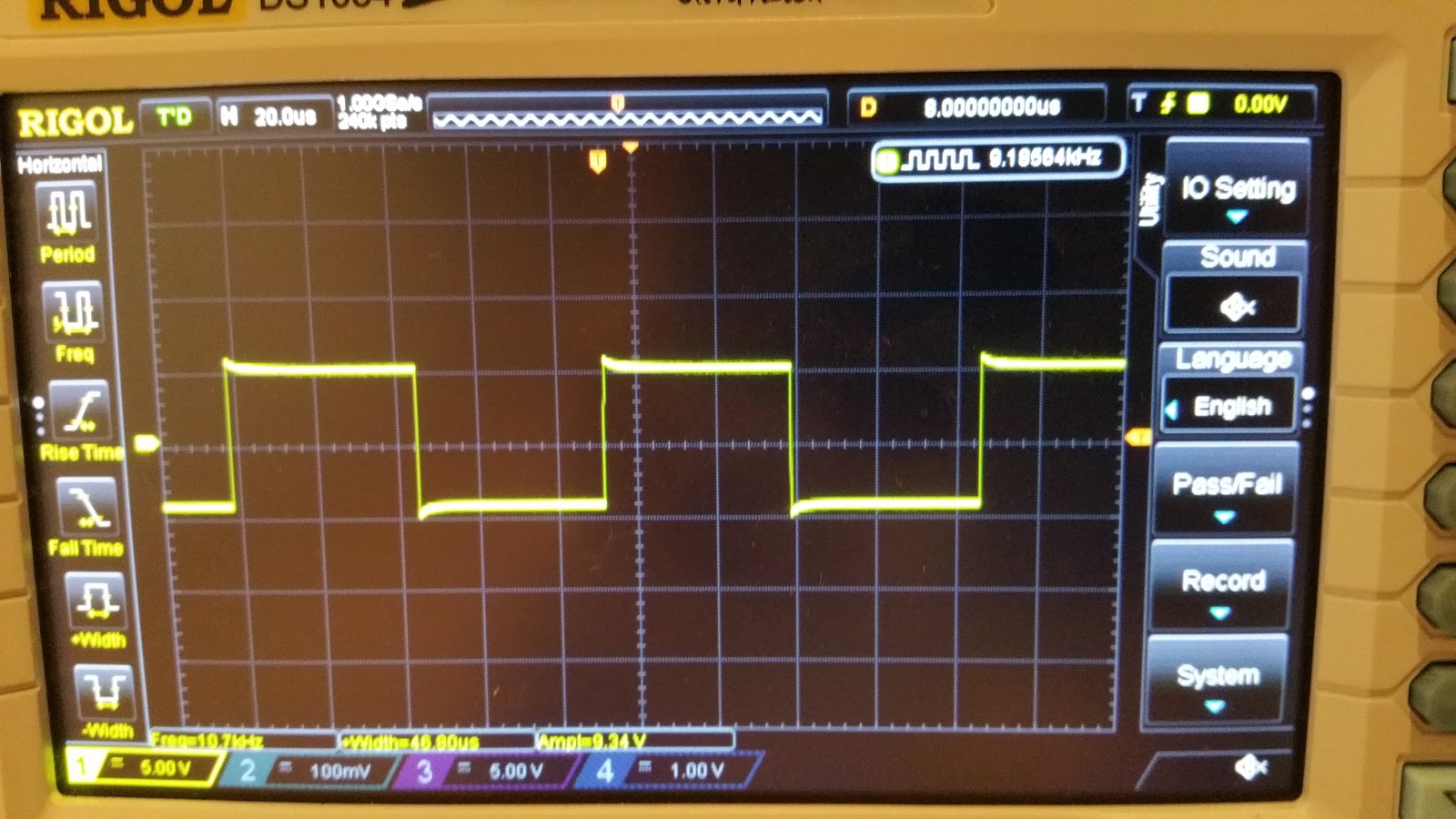
  Amplitude wise, looks like it can go as low as 100 mVpp and as high as 100 Vpp, all  into 50 Ohms. Yes, really. At least that's what my scope measures, anyway.
On the output BNC, it didn't mention anything about it being 50 Ohms, but I just presumed it was. Also, if I feed the output directly into the scope, without a 50 Ohm termination, the square waveforms look distorted. 

So, what else can this beast do? Well, it has you basic Sine, Square, Triangle and Pulse Width waveforms. Also, it has a nice and handy Burst Mode. As for the rest, I really can't say. I probably need  to RTFM.... If only I could find one that didn't cost more that what I paid for the unit itself.

And now, on to our scheduled Teardown:

The unit has a modular construction. And judging from the number of empty slots, looks like you could attach a whole freaking lot of options to this generator. Too bad I only got the basic version.


Next up is the PSU board. Amazingly enough, for a unit that's well over 30 years old, the caps look OK. All of them.


 The next board to get lifted out, after who knows how any years, is the A2 "Program Logic Card"


Looks like this is some glue logic, because the board if full of buffers, MUXs and other 74LS family logic.

Next up is the A20 - IEEE-488 interface card.


Starting from the left corner, there's a DIP switch, for setting the address of the device, two resistor networks (that's what Google came up with): 316A622 and 316A302, and a whole bunch of logic gates. 74LS family, of course.

Now we're starting to get into the meat of it. A7 - Question Mark Card


 Nope, no idea what "S/S" means or what it does. But it looks cool, doesn't it?
 Maybe signal conditioning? Or maybe it's something that has to do with the DC Offsets and stuff?

Next on the list is the A8 - Frequency Syhtesizer Card


You gotta love those hand drawn traces. Finally, we get to see some of that goodness I was hoping.
The digital part has the usual logic gates, flip-flops, etc. The analog part... well...
The main part is the AM26S02PC  Monostable Vibrator. 
This, together with that ferrite and  some  CA3039 diode arrays seem to make up what would be a ring modulator. I don't know too much about RF stuff or frequency symthesizers, so if anyone has a better idea of what the synthesizer might actually look loke, pleas leave a comment. I'm really interested in how this thing works. If only I had a manual for this thing.
Also, some keen observers might see that there's a whole boatload of diodes on this part of the board and I doubt they're all  Zeners.

The next board is the Waveform Selection A9 Card.


From the looks of things, it looks like the board is mainly switching some stuff in and out, i.e. ony selecting the appropriate waveform. The yellow cylinders are most likely relays and the two 8-pin ICs are DS75451N drivers, for said relays.
The bigger IC on the far right is a CA3086 transistor array.
The three single line ICs are resistor networks. One might speculate that these together with the diodes make up some snubber for the relays' coils. Though this is arguable.

The next card is the one that does all the heavy work -  The Output Amplifier A10 Card


Some bus interface logic, a few Motorola 2N5160 and 2N5109 RF transistors and some analog goodness make what is to be the generator's output board.
The front end of the amp is an RCA CA3102E differential amplifier IC.
Also notice the point-to-point connections in the third and fourth picture.

And last, but not least, we have the (Amp?) DAC card - A11


The usual bus interface and glue logic ICs. Boring.. But wait. What's this? an RCA  CA3130S. Now this is something. It's a metal can op-amp. But more that that, it's a PMOS input op-amp. Here's something you don't see every day. Well, I don't, anyway.
And some more Analog goodness - an  SN72558P op-amp
Ok, so maybe it's not something to write home about, but I thought I'd try and distract you fro the fact tht there is no actual DAC on this board. It might actually be on the board that's blted to the front panel. And I'm too lazy to actually take that out. Another option might be that all those resistors up there make an R-2R ladder DAC, but they all seem to have the same value, so that theory's shot.
So this board ight indeed be just a pre-amp for the signal coming from the DAC.

It looks like the reference is a simple 1 MHz crystal olscillator. I might consider changing that  to some TCXO or OCXO. We'll see.

Ok, so basically, I have a working unit, though there's still  a lot of loose ends to it. For starters the amplitude  and frequency are WAY off from what I set on the front panel.
For the frequency, there seems to be a ~2.5% to 3% deviation across all frequency ranges. For the output voltage.....well, the deviation is about 20 to 25% on all frequency ranges. 
These might be simple, except there's a whole heapin' mess of trimmers. Yes, you've guessed it.. I really need a mannual for this thing.

Here's a few mre pics of the beast in action:


In caase someone happens to have a manual for this thing and is willing to share, please contact me either by leaving a comment or on the blog's facebook page. Thanks.

If you'd like to see the full album of the teardown,  here it is.


    Later edit: Turns out that a kind sould  has the same model generator and was willing to share the manul with me and anyone else in need of it. You can download it from here.

Thanks Alexander!


google-site-verification: googlee8a41f51abde7545.html