Total Pageviews

Sunday, January 8, 2017

Interstate Electronics Corporation SPG-800 Signal Generator Teardown


      Well. it turns out that Christmas came a bit later this year. Probably  one of the reindeers had a flat hoof, or something.


  OK, so I bought myself a signal generator for the measly sum of 70 Euros, including shipping. The guy I bought it from said the unit didn't work. No problem, I said to  myself. It'll make a nice organ donor for other projects. Probably filled with all kinds of goodness inside.....matched JFET pairs maybe.... a nice 10 MHz reference. I was drooling over it.

Now, let me tell you, when it came, I almost had a hernia. It's heavy as frig....about 20 Kilos worth of 2 DIN (I guess) rackable signal generator.

   So, I got the beast in the house (all the way up to the 5th floor and no elevator, mind you) and first thing I looked at was the fuse....which, of course, was nice and toasted. Before replacing it, I looked at the mains voltage selection switch. My optimism spiked when I saw it was set to 230 V AC. 
So, now, knowing that the main transformer and PSU inside it might be OK, I replaced the fuse, turned it on and....nothing, obviously.

   So, following the "Thow shall always measure voltages" rule, I got the DMM out and first thing I measured was the input to the transformer. It measured 0 V on its input.
Seeing as how the on/off switch was all gooey, I measured the voltage on its pins. Nothing as well. 
Ok, I'll bite.... I preceeded to desolder the wires from the switch, rummaged through my junk pile and found a suitable replacement then soldered back the wires on that one. 
   Because I didn't find the appropriate fuse size, I cobbled something with I could find. No pretty, but it did the job.


  Yes, apparently, it was just that simple. So, now that I had a working Signal generator, let's see what it can do. 
The first thing I noticed when turning it on was how loud the fan was. It sounded as if I had a tractor plowing right next to me.

  Unfortunately, I couldn't fin any FREE user's manual or service manual for this unit. There is on on eBay for sale, but as of writing this , it cost about 80 dollars including shipping. Needless to say, the guy selling it can just shove it, I ain't paying that much. I;m sensible for these kinds of things.

  Ok, so from playing around with the unit, it looks like it can do a frequency range from about 10 mHz all the way up to (what should be) 10 MHz. If it goes higher, I couldn't find the right combination of random key presses tht made it go beyond 10 MHz.
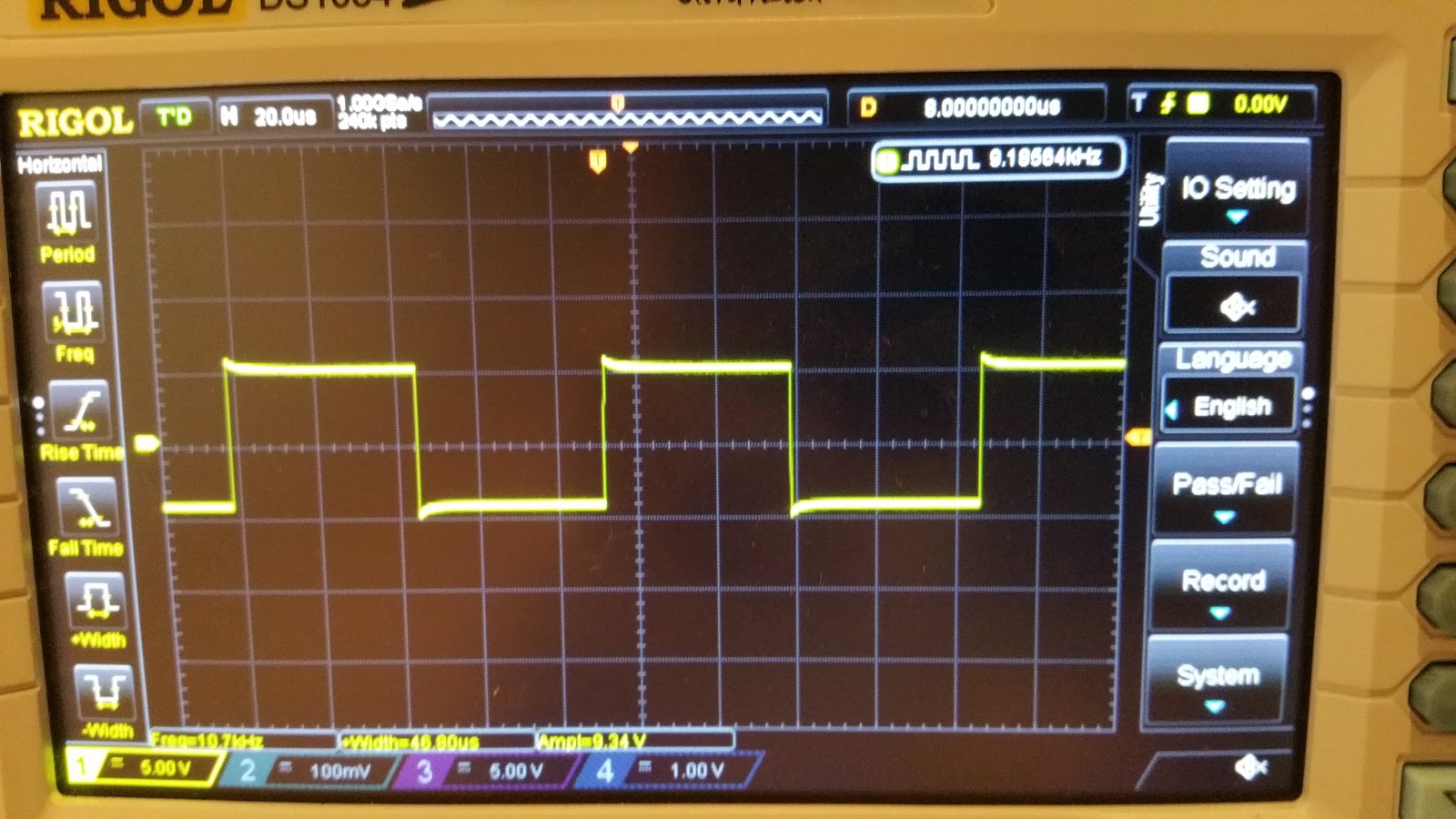
  Amplitude wise, looks like it can go as low as 100 mVpp and as high as 100 Vpp, all  into 50 Ohms. Yes, really. At least that's what my scope measures, anyway.
On the output BNC, it didn't mention anything about it being 50 Ohms, but I just presumed it was. Also, if I feed the output directly into the scope, without a 50 Ohm termination, the square waveforms look distorted. 

So, what else can this beast do? Well, it has you basic Sine, Square, Triangle and Pulse Width waveforms. Also, it has a nice and handy Burst Mode. As for the rest, I really can't say. I probably need  to RTFM.... If only I could find one that didn't cost more that what I paid for the unit itself.

And now, on to our scheduled Teardown:

The unit has a modular construction. And judging from the number of empty slots, looks like you could attach a whole freaking lot of options to this generator. Too bad I only got the basic version.


Next up is the PSU board. Amazingly enough, for a unit that's well over 30 years old, the caps look OK. All of them.


 The next board to get lifted out, after who knows how any years, is the A2 "Program Logic Card"


Looks like this is some glue logic, because the board if full of buffers, MUXs and other 74LS family logic.

Next up is the A20 - IEEE-488 interface card.


Starting from the left corner, there's a DIP switch, for setting the address of the device, two resistor networks (that's what Google came up with): 316A622 and 316A302, and a whole bunch of logic gates. 74LS family, of course.

Now we're starting to get into the meat of it. A7 - Question Mark Card


 Nope, no idea what "S/S" means or what it does. But it looks cool, doesn't it?
 Maybe signal conditioning? Or maybe it's something that has to do with the DC Offsets and stuff?

Next on the list is the A8 - Frequency Syhtesizer Card


You gotta love those hand drawn traces. Finally, we get to see some of that goodness I was hoping.
The digital part has the usual logic gates, flip-flops, etc. The analog part... well...
The main part is the AM26S02PC  Monostable Vibrator. 
This, together with that ferrite and  some  CA3039 diode arrays seem to make up what would be a ring modulator. I don't know too much about RF stuff or frequency symthesizers, so if anyone has a better idea of what the synthesizer might actually look loke, pleas leave a comment. I'm really interested in how this thing works. If only I had a manual for this thing.
Also, some keen observers might see that there's a whole boatload of diodes on this part of the board and I doubt they're all  Zeners.

The next board is the Waveform Selection A9 Card.


From the looks of things, it looks like the board is mainly switching some stuff in and out, i.e. ony selecting the appropriate waveform. The yellow cylinders are most likely relays and the two 8-pin ICs are DS75451N drivers, for said relays.
The bigger IC on the far right is a CA3086 transistor array.
The three single line ICs are resistor networks. One might speculate that these together with the diodes make up some snubber for the relays' coils. Though this is arguable.

The next card is the one that does all the heavy work -  The Output Amplifier A10 Card


Some bus interface logic, a few Motorola 2N5160 and 2N5109 RF transistors and some analog goodness make what is to be the generator's output board.
The front end of the amp is an RCA CA3102E differential amplifier IC.
Also notice the point-to-point connections in the third and fourth picture.

And last, but not least, we have the (Amp?) DAC card - A11


The usual bus interface and glue logic ICs. Boring.. But wait. What's this? an RCA  CA3130S. Now this is something. It's a metal can op-amp. But more that that, it's a PMOS input op-amp. Here's something you don't see every day. Well, I don't, anyway.
And some more Analog goodness - an  SN72558P op-amp
Ok, so maybe it's not something to write home about, but I thought I'd try and distract you fro the fact tht there is no actual DAC on this board. It might actually be on the board that's blted to the front panel. And I'm too lazy to actually take that out. Another option might be that all those resistors up there make an R-2R ladder DAC, but they all seem to have the same value, so that theory's shot.
So this board ight indeed be just a pre-amp for the signal coming from the DAC.

It looks like the reference is a simple 1 MHz crystal olscillator. I might consider changing that  to some TCXO or OCXO. We'll see.

Ok, so basically, I have a working unit, though there's still  a lot of loose ends to it. For starters the amplitude  and frequency are WAY off from what I set on the front panel.
For the frequency, there seems to be a ~2.5% to 3% deviation across all frequency ranges. For the output voltage.....well, the deviation is about 20 to 25% on all frequency ranges. 
These might be simple, except there's a whole heapin' mess of trimmers. Yes, you've guessed it.. I really need a mannual for this thing.

Here's a few mre pics of the beast in action:


In caase someone happens to have a manual for this thing and is willing to share, please contact me either by leaving a comment or on the blog's facebook page. Thanks.

If you'd like to see the full album of the teardown,  here it is.


    Later edit: Turns out that a kind sould  has the same model generator and was willing to share the manul with me and anyone else in need of it. You can download it from here.

Thanks Alexander!


Friday, November 4, 2016

TwinTeeth Plus Build Log - Part 1


I want a PCB and I want it NOW!

      Have you ever had a burning need to design, layout then etch a 2 sided prototype PCB, at home, before you send it out to a PCB fab, to make sure everything is OK?
Well, so have I.

      I came across a PCB "design bundle" that I really want to try out and  build. 
This will be  the first in a line of blog entries, detailing my build process and review of this. 
Because of it's open source nature (nice one guys, thanks!) I had everything I needed to modify and adapt my design to fit the parts that I had. 
Therefore, along with these posts I will also upload the files for the parts that I redid, just in case someone happens to have some of the parts that I had.

...but first, some background on this

      I've spent a few weeks looking around for ideas on how to PROPERLY make a device that moves on 2 or 3 axes and  has a UV laser for a head. I wanted this to do a line-scan on a UV resin-coated PCB board, then etch it and have a prototype PCB done in  a matter of 30-60 minutes.
I quickly came to the conclusion that a  traditional gantry-style  CNC machine wouldn't cut it, in terms of speed.

      So, thinking about other stuff that has a scanning laser, I thought about how fast laser printers work. Then I began looking at trying to control a mirror array from an actual laser printer. 
In theory, it wouldn't be hard at all. Just have a hexagonal mirror spin on a spindle, shine a UV laser on it then pulse the laser so it will scan the board one line at a time. But, as always, the devil is in the details. 


      Suppose you have a PCB that's 10cm x 10cm. The laser position is fixed. All you're doing is generating a scanning pattern with the hexagonal mirror. That means, that relative to the center point of the PCB,  the laser beam will have to travel 5 cm in each direction (5 to the left and 5 to the right). This means that the beam length will be altered by ± 5 cm. 
According to physics, if the length of the beam changes, that means that the focusing of the beam will change also. 
What that means is, with a fixed focus, as would be the case in a scanning head, the beam will be focused in the middle of the board and it will be slightly out of focus on the edges of the board. If you have a laser beam that is not properly focused, it will leave behind an image that is blurry. 
And if you're doing  a board with, say, 0603 components on it, the pads will come out looking more like blobs of copper.

      Of course, laser printers have the same issue. The way THEY solve this is  they have  an  f-Theta lens in the beam path.
      For those of us that don't have Stephen Hawking  on speed-dial, an "f-Theta" lens  will take the incoming FOCUSED  beam of light and keep it focused, no matter the angle it's outputted at (or, put it another way, along the scanning path,  the beam, it will be focused in any point)

                                        Source: http://www.opli.net/opli_magazine/eo/2014/optotune-demonstrates-new-laser-processing-lens-aug-news/

...Houston, we have a Problem!

      So, let's just Google "UV f-theta" lens and see what we'v....OH MY GOD!!!  How much?? F*** it! I'm taking up ballet lessons.

So, after I drank a cup of water, took a few Xanax pills and did that "Wax on wax off" move, I decided that I had to go back to the initial gantry style of CNC machine.

Note: for those curious enough to ask, a laser printer uses a RED laser. The PLASTIC f-Theta lens in a laser printer is NOT suited at all for the UV laser. The plastic the lens is made of  is not transparent to UV light.

...Long story short....

    So, eventually,  after searching the net for all kinds of ways to solve this, I found this site: http://www.diyouware.com/DiyoPCB-MKI and my jaw just dropped. Now, how about that... that was EXACTLY what I wanted to build.

But first thing's first: let me congratulate the guys (and gals?) over at Diyouware.com for their hard work. Hope to see you in a Kickstarter campaign soon enough.
And no, I'm not in any way affiliated with them nor am I getting any money from them for writing this.
So, with the disclaimers out of the way, on with the story...
     I  began reading what these fellows did and how they hacked the Blu-ray laser head of the Toshiba drive. Of course, I contacted d the guys, and they recommended me the TwinTeeth variant of the PCB factory. The reason was that the original Mk1 design was kind of clunky and plagued with problems generated by vibrations.

Let's get building

      Now, I have to say, I really appreciate what these guys have done. They did everything from scratch, even developing their own hardware and software platform. 
And they've open sourced everything as well. To me, this is awesome, as everyone can get the files and make their own build, modifying it where possible and putting their own spin on things. So guys, a big  thumbs up from me!

I've decided on building the TwinTeeth Plus version, as this has less 3D printed parts and to me, looks to be more stable mechanical wise.

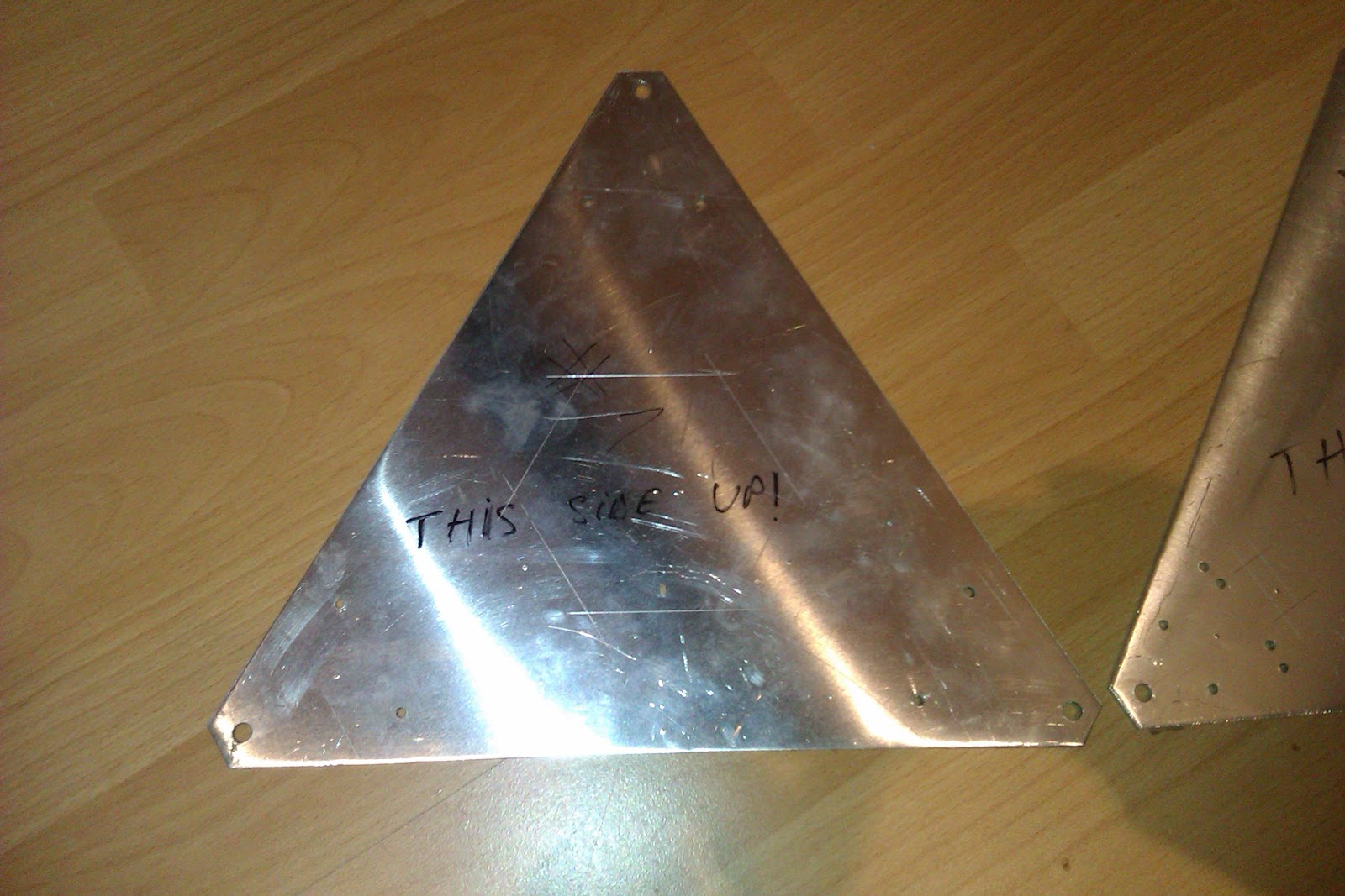
First off, I got me some 2 mm thick aluminium sheet (I couldn't find any 3mm plate)


On these, I glued (OK, scotch taped) the paper templates then marked where the holes would go.

After this, I went to print the 3 motor holders that the delta sits on. And here is where the real fun begins...
Looking through my collection of stepper motors, I happened to find 3 identical NEMA23 steppers. 

 The original TwinTeeth  needed NEMA17....Yes, this is one of the advantages of having a mechanical engineer for a girlfriend (Thank you!) She helped me modify the motor holder .STL file, so that it took the NEMA23 motors.


Next up were the bottom lead screw supports. Some F6900ZZ flanged bearings were supposed to be fitted into them. 
Because these bearings seemed to proliferate in the wild planes of eBay, but nowhere near my country and because I got burned by the national postal service (which sucks) too many times,I decided I would replace the flanged bearings for "normal" ones. (flanged bearing was d=10 mm, D=22 mm, 6 mm width; replacement bearing is d=10 mm, D=26 mm, 8 mm width)
 This meant firing up Solidworks and doing my magic. (I was stubborn enough that I wanted to do the part from scratch, by myself - what better way of learning Solidworks)


Unfortunately, the original dimensions in the .STL files have some wacky values, which proved to be a real pain to replicate. I had to build my own geometry on top of the .STL par to get the dimensions I needed. Then replicated and adapted that so  a 6000ZZ series bearing would fit.

Next, I got hold of some 20mm x 20mm square aluminium profile for the legs, 3x10mm, 200mm long  ACME (AKA trapezoidal) screws which I ordered to be milled on one end to 8mm, so it would fit in a 6.35mm x 8mm flexible coupling and  6 x 6mm, 300mm long guide rails, which I ordered to have M4 bolt holes drilled and tapped into them, at each end.


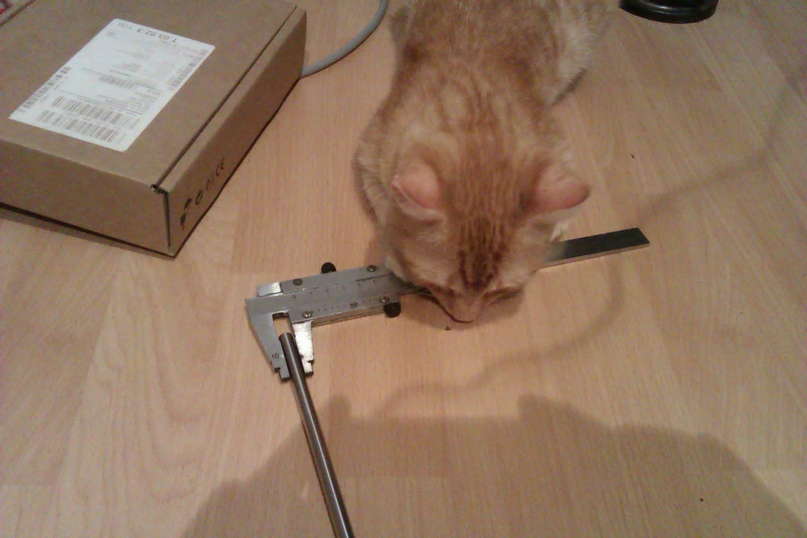
I also got some extra help for this build


He knows the vernier scale can be tough to read sometimes, so any help is welcomed.

Also, I know, the picture quality is really crappy.... I gotta get me one of those newfangled things called a camera. Tin-type photos, anyone?

Inches, millimeters, mills, centimeters....

      The only thing I found difficult about this project so far is modifying the existing parts. It's not that they're in .STL format.... it's the fact that the dimensions are kind of all over the shop.
At least, this is what I gather from measuring the provided .DWG files and the original .STL models. I mean, there are hardly any measurements that seem to have nice round values. I don't know if this is due to the fact that the design was done in inches, then converted to mm, or something else is going on, but it makes things kind of hard when it comes to taking measurements.

...come one, come all....

       This is the link to the GitHub page that contains the modified files. Like I said, I used NEMA23 steppers and  6000ZZ bearings and some of the 3D prints were modified for  MY specific build.
  As the build will continue, I will modify other parts as well. Why? Because it's interesting and because I have  an OCD about improving stuff.
Next will probably be the ACME nut for the 10 mm screws. I don't know if  a bough ACME nut will have more or less backlash than the original TwinTeeth method, where a mold of the screw was made and used as a nut, but those linear bearings held to the mount with  zip-ties...kinda make my skin crawl. 


google-site-verification: googlee8a41f51abde7545.html